12.3
Operation
12.3.1
A/D Conversion Operation
The A/D converter operates by successive approximations, and yields its conversion result as 10-
bit data.
A/D conversion begins when software sets the A/D start flag (bit ADSF) to 1. Bit ADSF keeps a
value of 1 during A/D conversion, and is cleared to 0 automatically when conversion is complete.
The completion of conversion also sets bit IRRAD in interrupt request register 2 (IRR2) to 1. An
A/D conversion end interrupt is requested if bit IENAD in interrupt enable register 2 (IENR2) is
set to 1.
If the conversion time or input channel needs to be changed in the A/D mode register (AMR)
during A/D conversion, bit ADSF should first be cleared to 0, stopping the conversion operation,
in order to avoid malfunction.
12.3.2
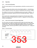
Start of A/D Conversion by External Trigger Input
The A/D converter can be made to start A/D conversion by input of an external trigger signal.
External trigger input is enabled at pin ADTRG when bit IRQ4 in PMR1 is set to 1 and bit TRGE
in AMR is set to 1. Then when the input signal edge designated in bit IEG4 of interrupt edge
select register (IEGR) is detected at pin ADTRG, bit ADSF in ADSR will be set to 1, starting A/D
conversion.
Figure 12-2 shows the timing.
ø
Pin ADTRG
(when bit
IEG4 = 0)
ADSF
A/D conversion
Figure 12-2 External Trigger Input Timing
338

 ETC [ ETC ]