9.7.5
Application Notes
1. When reading the values in ECH and ECL, first clear bits CUEH and CUEL to 0 in ECCSR to
prevent asynchronous event input to the counter. The correct value will not be returned if the
event counter increments while being read. Note that ECH and ECL counter may be
incremented by 1 when clearing CUEH and CUEL to 0 in ECCSR.
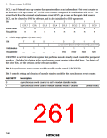
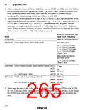
2. The maximum clock frequencies to be input to AEVH and AEVL pins with the internal power
supply step-down circuir not used are: 6 MHz when VCC = 4.5 to 5.5 V, 4 MHz when VCC = 3.0
to 5.5V, and 3.2 MHz when VCC = 2.6 to 5.5 V. The maximum clock frequency with the
internal power supply step-down circuit used is 2 MHz when VCC = 2.2 to 5.5 V. Otherwise,
ensure that the maximum frequency is 1 MHz. In addition, ensure that the high and low widths
of the clock are at least 83 ns. The duty cycle is immaterial.
Maximum AEVH/AEVL Pin
Mode
Input Clock Frequency
When not using the internal
step-down circuit
16-bit mode
8-bit mode Active (high-speed), sleep (high-speed)
VCC = 4.5 to 5.5 V/6 MHz
VCC = 3.0 to 5.5 V/4 MHz
VCC = 2.6 to 5.5 V/3.2 MHz
VCC = 2.2 to 5.5 V/2 MHz
Others/1 MHz
When using the internal
step-down circuit
VCC = 2.2 to 5.5 V/2 MHz
Others/1 MHz
8-bit mode Active (medium-speed), sleep (medium-speed) (ø/16) 2 · fOSC
(ø/32) fOSC
(ø/64) 1/2 · fOSC
fOSC = 400 kHz to 4 MHz
(ø/128) 1/4 · fOSC
(øw/2) 1000 kHz
(øw/4) 500 kHz
(øw/8) 250 kHz
8-bit mode Watch, subactive, subsleep, standby
øw = 32.768 kHz or 38.4 kHz
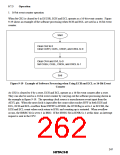
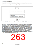
3. When using the clock in the 16-bit mode, set CUEH to 1 first, then set CRCH to 1 in ECCSR.
Or, set CUEH and CRCH simultaneously before inputting the clock. After that, do not change
the CUEH value while using in the 16-bit mode. Otherwise, an error counter increment may
occur.
250

 ETC [ ETC ]