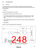
3. Register configuration
Table 9-17 shows the register configuration of the watchdog timer.
Table 9-17 Watchdog Timer Registers
Name
Abbrev.
TCSRW
TCW
R/W
R/W
R/W
R/W
R/W
Initial Value
H'AA
Address
H'FFB2
H'FFB3
H'FFFB
H'FFCA
Timer control/status register W
Timer counter W
H'00
Clock stop register 2
Port mode register 3
CKSTP2
PMR3
H'FF
H'00
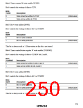
9.6.2
Register Descriptions
1. Timer control/status register W (TCSRW)
Bit
7
B6WI
1
6
TCWE
0
5
4
3
2
WDON
0
1
0
B4WI TCSRWE B2WI
B0WI
WRST
0
Initial value
Read/Write
1
0
1
1
*
*
*
*
R/W
R
R/W
R
R/W
R
R/W
R
Note: * Write is permitted only under certain conditions, which are given in the descriptions of
the individual bits.
TCSRW is an 8-bit read/write register that controls write access to TCW and TCSRW itself,
controls watchdog timer operations, and indicates operating status.
Bit 7: Bit 6 write inhibit (B6WI)
Bit 7 controls the writing of data to bit 6 in TCSRW.
Bit 7
B6WI
Description
0
1
Bit 6 is write-enabled
Bit 6 is write-protected
(initial value)
This bit is always read as 1. Data written to this bit is not stored.
234

 ETC [ ETC ]