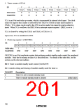
2. Block diagram
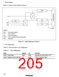
Figure 9-2 shows a block diagram of timer C.
TMC
UD
TCC
TLC
ø
PSS
TMIC
øW/4
IRRTC
Notation:
TMC : Timer mode register C
TCC : Timer counter C
TLC
: Timer load register C
IRRTC : Timer C overflow interrupt request flag
PSS : Prescaler S
Figure 9-2 Block Diagram of Timer C
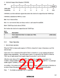
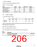
3. Pin configuration
Table 9-5 shows the timer C pin configuration.
Table 9-5 Pin Configuration
Name
Abbrev.
I/O
Function
Timer C event input
TMIC
Input
Input
Input pin for event input to TCC
Timer C up/down select
Timer C up/down-count selection UD
190

 ETC [ ETC ]