Si3035
APPENDIX—UL1950 3RD EDITION
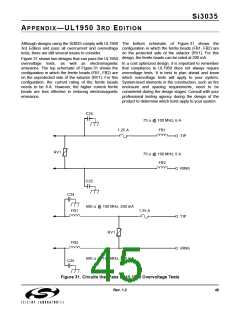
Although designs using the Si3035 comply with UL1950 The bottom schematic of Figure 31 shows the
3rd Edition and pass all overcurrent and overvoltage configuration in which the ferrite beads (FB1, FB2) are
tests, there are still several issues to consider.
on the protected side of the sidactor (RV1). For this
design, the ferrite beads can be rated at 200 mA.
Figure 31 shows two designs that can pass the UL1950
overvoltage tests, as well as electromagnetic In a cost optimized design, it is important to remember
emissions. The top schematic of Figure 31 shows the that compliance to UL1950 does not always require
configuration in which the ferrite beads (FB1, FB2) are overvoltage tests. It is best to plan ahead and know
on the unprotected side of the sidactor (RV1). For this which overvoltage tests will apply to your system.
configuration, the current rating of the ferrite beads System-level elements in the construction, such as fire
needs to be 6 A. However, the higher current ferrite enclosure and spacing requirements, need to be
beads are less effective in reducing electromagnetic considered during the design stages. Consult with your
emissions.
professional testing agency during the design of the
product to determine which tests apply to your system.
C24
75 Ω @ 100 MHz, 6 A
1.25 A
FB1
TIP
RV1
75 Ω @ 100 MHz, 6 A
FB2
RING
C25
C24
600 Ω @ 100 MHz, 200 mA
FB1
1.25 A
TIP
RV1
FB2
RING
600 Ω @ 100 MHz, 200 mA
C25
Figure 31. Circuits that Pass all UL1950 Overvoltage Tests
Rev. 1.2
45

 ETC [ ETC ]