Si3035
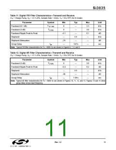
Table 11. Digital FIR Filter Characteristics—Transmit and Receive
(V = Charge Pump, V = +5 V ±5%, Sample Rate = 8 kHz, T = 0 to 70°C for K-Grade)
A
D
A
Parameter
Symbol
F(0.1 dB)
F(3 dB)
Min
0
Typ
—
Max
3.3
3.6
0.1
—
Unit
kHz
kHz
dB
Passband (0.1 dB)
Passband (3 dB)
Passband Ripple Peak-to-Peak
Stopband
0
—
–0.1
—
—
4.4
—
kHz
dB
Stopband Attenuation
Group Delay
–74
—
—
tgd
12/Fs
—
sec
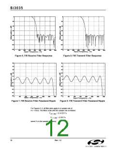
Note: Typical FIR filter characteristics for Fs = 8000 Hz are shown in Figures 6, 7, 8, and 9.
Table 12. Digital IIR Filter Characteristics—Transmit and Receive
(V = Charge Pump, V = +5 V ±5%, Sample Rate = 8 kHz, T = 0 to 70°C for K-Grade)
A
D
A
Parameter
Symbol
Min
0
Typ
—
Max
3.6
0.2
—
Unit
kHz
dB
F(3 dB)
Passband (3 dB)
Passband Ripple Peak-to-Peak
Stopband
–0.2
—
—
4.4
kHz
dB
Stopband Attenuation
Group Delay
–40
—
—
—
tgd
1.6/Fs
—
sec
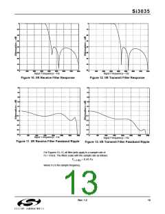
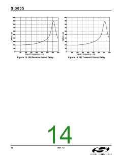
Note: Typical IIR filter characteristics for Fs = 8000 Hz are shown in Figures 10, 11, 12, and 13. Figures 14 and 15 show
group delay versus input frequency.
Rev. 1.2
11

 ETC [ ETC ]