Another consideration is that the interpolator receives a 12-bit input from
the Nyquist filter. Set the shifter in the Nyquist filter accordingly (for
example: 2). For PLL Mode 2, the shifter value (which is defined in the
filter coefficients in Register 0 of Group 2) is 3; for Mode 1, the shifter
value is 5.
2.14 Serial Microprocessor Interface
The external microprocessor controls the QAM modes of operation, 16
to 256 QAM. It also controls the mode of input synchronization, that is,
whether to lock synchronization to sync bytes or input pulses. The
microprocessor interface downloads the filter coefficients and the delay
value for proper FIFO initialization.
2
The microprocessor interface uses an I C-compatible serial control
protocol. The signal behavior is described in Appendix A. The interface
is slave-only and can not be a master to the serial bus. The base address
of the component is composed of a fixed five-bit address and two
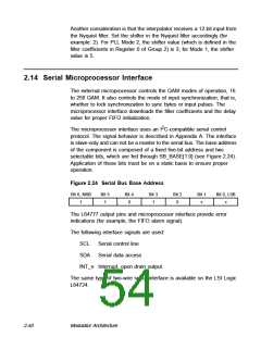
selectable bits, which are fed through SB_BASE[1:0] (see Figure 2.24).
Application of these bits must be on a static basis to ensure proper
operation.
Figure 2.24 Serial Bus Base Address
Bit 6, MSB
1
Bit 5
1
Bit 4
0
Bit 3
1
Bit 2
0
Bit 1
x
Bit 0, LSB
x
The L64777 output pins and microprocessor interface provide error
indications (for example, the FIFO alarm signal).
The following interface signals are used:
SCL
SDA
Serial control line
Serial data access
INT_n Interrupt, open drain output
The same type of two-wire serial interface is available on the LSI Logic
L64724.
2-40
Modulator Architecture

 ETC [ ETC ]