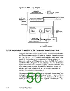
Figure 2.22 NCO Loop Diagram
NPCLK,
Frequency
N_COUNT, NP_COUNT,
NM_COUNT
Measurement Unit
Step Correction
ICLK
Virtual FIFO for Automatic
Frequency Acquisition
58
If Serial
Threshold
Byte Clock
Phase Loop
CNT_I
Divider
CNT_O
Divider
OCLK
Interpolator
Ctrl
EXOR
phase_gain
enable_phase_loop = 1
NCO
Step
(for Frequency Selection)
2.12.2 Acquisition Phase Using the Frequency Measurement Unit
During the acquisition phase, the NCO bases the measurement on the
assumption that the byte clock on the ICLK input has a duration of either
of n − 1, n, or n + 1 PCLK cycles and that the input stays within these
bounds for the duration of the measurement. You can program the
duration in multiples of 256-byte clock cycles in the REF_DUR register
(see Section 4.2.7, “Registers 21 and 22,” page 4-14). The NCO control
register (see Section 4.2.3, “Register 14,” page 4-12) can control the start
of the measurement, and the Measurement Done bit in register 13
indicates successful completion. If bit 2 of Register 14 enables an
interrupt, the measurement generates it.
After completion of the measurement, the host reads the number of byte
clock cycles found with the appropriate length of n, n + 1 and n − 1 (from
NM_COUNT, N_COUNT, NP_COUNT—see Sections 4.2.10 through
4.2.12), as well as the value of n (from N_PCLK—see Section 4.2.9).
2-36
Modulator Architecture

 ETC [ ETC ]