The abbreviations in the illustration indicate the following states:
•
S0 is the sync pattern research state. When S is detected, transition
a0 leads to state S1. If S is not detected, transition b0 maintains
state S0.
•
S1 is a retest state. Period (P) bytes after S detection in state S0,
the detection of S is retested. If S is detected again, transition “a”
leads to state S2. If S is not detected, transition “b” leads back to
state S0.
•
S2 again tests detection of S after period P. If correct detection
occurs, transition “a” leads to the sync tracking phase. If not,
transition “b” leads back to S0.
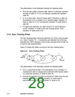
2.4.2 Sync Tracking Phase
The sync tracking phase checks the detection of S at the correct location
(i.e., every P bytes). TS − 1 mismatches are tolerated, but at the last
mismatch the L64777 declares a loss-of-sync and goes back to state S0
to look for new synchronization.
Figure 2.8 shows the states occurring in the sync tracking phase.
Figure 2.8 Sync Tracking Phase
a
b
a
b
b
From
State S2
S3
S4
a
S5
a
To
State S0
The abbreviations in the illustration indicate the following states:
•
S3 is a synchronized state. If no mismatches occur, transition “a”
maintains this state. If a wrong word is detected at the location where
S is expected, transition “b” leads to state S4.
•
S4 tests the detection of S after an interval of P bytes since the last
detection test. If S is detected, transition “a” leads back to
synchronized state S3. If not, transition “b” leads to S5.
2-14
Modulator Architecture

 ETC [ ETC ]