Register Description
3.4
PCI-to-PCI Bridge Registers (Device 1)
The configuration space for device #1 is controlled by the AGP_DIS bit in the PMCR register.
Note: When AGP_DIS = 0, the configuration space for device #1 is enabled, and the registers defined
below are accessible through the configuration mechanism defined in the first section of this
document.
Note: When the AGP_DIS = 1, the configuration space for device #1 is disabled. All configuration cycles
(reads and writes) to device #1 of bus 0 will cause the master abort status bit for device #0/ bus 0 to
be set. Configuration read cycles will return data of all 1’s. Configuration write cycles will have no
effect on the registers.
Table 3-4. 82443BX Configuration Space—Device 1
Address
Offset
Register
Symbol
Default
Value
Register Name
Access
RO
00–01h
02–03h
04–05h
06–07h
08h
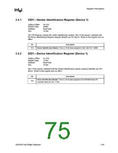
VID1
Vendor Identification
8086h
DID1
Device Identification
7191h
0000h
0220h
00/01h
00h
RO
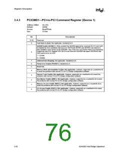
PCICMD1
PCISTS1
RID1
PCI Command Register
PCI Status Register
R/W
RO, R/WC
RO
Revision Identification
Reserved
09h
—
—
0Ah
SUBC1
BCC1
—
Sub-Class Code
04h
RO
0Bh
Base Class Code
06h
RO
0Ch
Reserved
00h
—
0Dh
MLT1
Master Latency Timer
Header Type
00h
R/W
RO
0Eh
HDR1
—
01h
0F–17h
18h
Reserved
00h
—
PBUSN
SBUSN
SUBUSN
SMLT
Primary Bus Number
Secondary Bus Number
Subordinate Bus Number
Secondary Bus Master Latency Timer
I/O Base Address Register
I/O Limit Address Register
Secondary PCI-to-PCI Status Register
Memory Base Address Register
Memory Limit Address Register
Prefetchable Memory Base Address Reg.
Prefetchable Memory Limit Address Reg.
Reserved
00h
RO
19h
00h
R/W
R/W
R/W
R/W
R/W
R/WC, RO
R/W
R/W
R/W
R/W
c
1Ah
00h
1Bh
00h
1Ch
IOBASE
IOLIMIT
SSTS
MBASE
MLIMIT
PMBASE
PMLIMIT
—
F0h
1Dh
00h
1E–1Fh
20–21h
22–23h
24–25h
26–27h
28–3Dh
3Eh
02A0h
FFF0h
0000h
FFF0h
0000h
0
BCTRL
—
Bridge Control Register
Reserved
80h
R/W
—
3F–FFh
00h
3-48
82443BX Host Bridge Datasheet

 ETC [ ETC ]