Signal Description
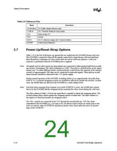
Table 2-9. Reference Pins
Name
Description
GTLREF[B:A] GTL Buffer voltage reference input
VTT[B:A]
VCC
GTL Threshold voltage for early clamps
Power pin @ 3.3V
VSS
Ground
REF5V
AGPREF
PCI 5V reference voltage (for 5V tolerant buffers)
External Input Reference
2.7
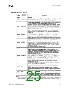
Power-Up/Reset Strap Options
Table 2-10 is the list of all power-up options that are loaded into the 82443BX during cold reset.
The 82443BX is required to float all the signals connected to straps during cold reset and keep
them floated for a minimum of 4 host clocks after the end of cold reset sequence. Cold reset
sequence is performed when the 82443BX power is applied.
Note: All signals used to select power-up strap options are connected to either internal pull-down or pull-
up resistors of minimum 50K ohms (maximum is 150K). That selects a default mode on the signal
during reset. To enable different modes, external pull ups or pull downs (the opposite of the internal
resistor) of approximately 10K ohm can be connected to particular signals. These pull up or pull
down resistors should be connected to the 3.3V power supply.
During normal operation of the 82443BX, including while it is in suspend mode, the paths from
GND or Vcc to internal strapping resistors are disabled to effectively disable the resistors. In these
cases, the MAB# lines are driven by the 82443BX to a valid voltage levels.
Note: Note that when resuming from suspend, even while PCIRST# is active, the MAB# lines remain
driven by the 82443BX and the strapping latches maintain the value stored during the cold reset.
This first column in Table 2-10 lists the signal that is sampled to obtain the strapping option. The
second column shows which register the strapping option is loaded into. The third column is a
description of what functionality the strapping selects.
The GTL+ signals are connected to the VTT through the normal pull-ups. CPU bus straps
controlled by the 82443BX (e.g. A7# and A15#), are driven active at least six clocks prior to the
active-to-inactive edge of CPURST# and driven inactive four clocks after the active-to-inactive
edge of the CPURST#.
2-10
82443BX Host Bridge Datasheet

 ETC [ ETC ]