Signal Description
Signal Description
2
This chapter provides a detailed description of 443BX signals. The signals are arranged in
functional groups according to their associated interface.
The “#” symbol at the end of a signal name indicates that the active, or asserted state occurs when
the signal is at a low voltage level. When “#” is not present after the signal name the signal is
asserted when at the high voltage level.
The following notations are used to describe the signal type:
I
Input pin
O
Output pin
OD
Open Drain Output pin. This pin requires a pullup to the VCC of the processor core
I/OD Input / Open Drain Output pin. This pin requires a pullup to the VCC of the processor
core
I/O
Bi-directional Input/Output pin
The signal description also includes the type of buffer used for the particular signal:
GTL+ Open Drain GTL+ interface signal. Refer to the GTL+ I/O Specification for complete
details
PCI
PCI bus interface signals. These signals are compliant with the PCI 3.3V and 5.0V
Signaling Environment DC and AC Specifications
AGP
AGP interface signals. These signals are compatible with AGP 3.3V Signaling
Environment DC and AC Specifications
CMOS The CMOS buffers are Low Voltage TTL compatible signals. These are 3.3V only.
2.1
Host Interface Signals
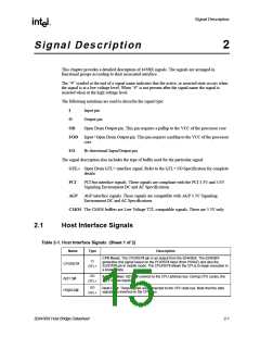
Table 2-1. Host Interface Signals (Sheet 1 of 2)
Name
Type
Description
CPU Reset. The CPURST# pin is an output from the 82443BX. The 82443BX
generates this signal based on the PCIRST# input (from PIIX4E) and also the
SUSTAT# pin in mobile mode. The CPURST# allows the CPUs to begin execution in
a known state.
O
CPURST#
GTL+
I/O
Address Bus: A[31:3]# connect to the CPU address bus. During CPU cycles, the
A[31:3]# are inputs.
A[31:3]#
GTL+
I/O
Host Data: These signals are connected to the CPU data bus. Note that the data
signals are inverted on the CPU bus.
HD[63:0]#
GTL+
82443BX Host Bridge Datasheet
2-1

 ETC [ ETC ]