CPD-E200E
SECTION 4
ADJUSTMENTS
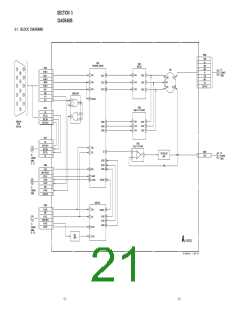
Connect the communication cable of the computer to the connector located on the D board on the monitor. Run the service software
and then follow the instruction.
1 1-690-391-21
2 A-1500-819-A
Interface Unit
3 3-702-691-01
Connector Attachment
IBM AT Computer
as a Jig
To BUS CONNECTOR
D-sub
(9 Pin [female])
mini Din
(8Pin)
4 Pin
4 Pin
4 Pin
*The parts above (
) are necessary for DAS adjustment.
3
1
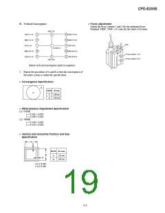
• Landing Rough Adjustment
1. Enter the full white signal. (or the full black dots signal)
2. Set the contrast to “CONT”=MAX.
8. Adjust each top and bottom pins by two wedges and then not
swing DY neck right and left. Adjust H. Trap to become
horizontal trapezoid(c = d).
3. Make the screen monogreen.
(When fixing DY with wedges, insert wedges completely so
that the DY does not shake.)
Note: Off the outputs from R ch and B ch of SG.
4. Reverse the DY, and adjust coarsely the purity magnet so
that a green raster positions in the center of screen.
5. Moving the DY forward, adjust so that an entire screen be-
comes monogreen.
a
“a” and “b” must be equal, and
d
c
“c” and “d” must be equal.
6. Adjust the tilt of DY, and fix lightly with a clamp.
Note: "TILT" shall be set at 0
b
<How to drive in wedges>
• Landing Fine Adjustment
1. Put the set inside the Helmholtz coil.
2. Input the single green signal.
3. Demagnetize the CRT surface with the hand degausser , and
perform auto degaussing.
4. Attach the wobbling coil to the designated part of the CRT
neck.
5. Attach the sensor of the landing adjustment unit on the CRT
surface.
9. If the L/D is not within the standards adjust purity magnet
and in front and behind of DY to satisfy L/D adjustment
standards. If the corner is not within the standards, adjust
disc magnet to satisfy L/D adjustment standards.
Note:
Purity Magnet
<<Zero Position>>
(1) When necessary to paste magnets more than 2 pieces, be
careful that the convergence and the distortion would be al-
terable.
(2) Paste within 80 to 120 mm from the DY on the diagonal line
of the magnet.
10. If using the magnet, be sure to demagnetize with the de-
gausser and check.
11. Remove the sensor and wobbling coil.
12. Check that the DY is not tilting.
Purity magnet position
L/D control specification
± 5
± 5
± 5
± 7
± 7
± 7
± 5
± 5
± 5
6. Adjust the DY position and purity, and the DY tilt.
7. Fasten DY with screw.
Note: Torque 22 ±2kgcm (2.2 ± 0.2 Nm)
4-1

 ETC [ ETC ]