CPD-E200E
SECTION 3
SAFETY RELATED ADJUSTMENT
When replacing or repairing the shown below table, the
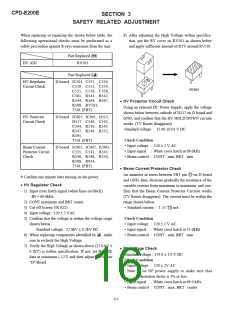
8) After adjusting the High Voltage within specifica-
tion, put the RV cover on RV501 as shown below
and apply sufficient amount of RTV around RV501.
following operational checks must be performed as a
safety precaution against X-rays emissions from the unit.
Part Replaced ([)
HV ADJ
RV501
Part Replaced (])
1 0 4
HV Regulator
Circuit Check
D board IC501, C532, C534,
C539, C553, C554,
C555, C556, C558,
C561, R541, R542,
R544, R564, R567,
R568, RV501,
RV501
• HV Protector Circuit Check
Using an external DC Power Supply, apply the voltage
shown below between cathode of D517 on D board and
GND, and confirm that the HV HOLD DOWN circuite
works. (TV Raster disappears)
T501 (FBT)
HV Protector
Circuit Check
D board IC607, IC901, D515,
D517, C540, C542,
C544, R510, R543
R547, R549, R552,
R595,
Standard voltage : 35.80 ±0.01 V DC
Check Condition
T501 (FBT)
• Input voltage : 120 ± 2 V AC
• Input signal : White cross hatch at 69.0kHz
• Beam control : CONT : min, BRT : min
Beam Current
Protector Circuit
Check
D board IC605, IC607, IC901,
C535, C541, R545,
R546, R548, R550,
R596, R934,
T501 (FBT)
• Beam Current Protector Check
An ammeter in series between FBT pin !] on D board
and GND, then, decrease gradually the resistance of the
variable resistor from maximum to minimum, and con-
firm that the Beam Current Protector Circuite works
(TV Raster disappears). The current must be within the
range shown below.
Confirm one minute later turning on the power.
*
• HV Regulator Check
1) Input cross hatch signal (white lines on black).
: fH = 69.0kHz
2) CONT maximum and BRT center.
3) Cut off Screen VR (G2).
• Standard current : 1.55 +-00..1000 mA
4) Input voltage : 120 ± 2 VAC
5) Confirm that the voltage is within the voltage range
shown below.
Check Condition
• Input voltage : 120 ± 2 V AC
• Input signal : White cross hatch at 31.0kHz
• Beam control : CONT : min, BRT : min
Standard voltage : 27.0kV ± 0.2kV DC
6) When replacing components identified by ] , make
sure to recheck the High Voltage.
7) Verify the High Voltage as shown above (27.0 kV ±
0.2kV) is within specification. If not, set H. SIZE
data at minimum (-127) and then adjust RV501 on
"D" Board.
• B+ Voltage Check
Standard voltage : 179.0 ± 3.0 V DC
Check Condition
• Input voltage : 120 ± 2V AC
Note : Use NF power supply or make sure that
distortion factor is 3% or less.
• Input signal : White cross hatch at 69.0 kHz
• Beam control : CONT : max, BRT : center
3-1

 ETC [ ETC ]