eZ80L92 MCU
Product Specification
86
Timer Reload Registers—High Byte
The Timer Reload Register—High Byte, detailed in Table 36, stores the most significant
byte (MSB) of the 2-byte timer reload value. In CONTINUOUS mode, the timer reload
value is reloaded into the timer upon end-of-count. When RST_EN (TMRx_CTL[1]) is set
to 1 to enable the automatic reload and restart function, the timer reload value is written to
the timer on the next rising edge of the clock.
Note:
The Timer Data registers and Timer Reload registers share the same address space.
Table 36. Timer Reload Registers—High Byte (TMR0_RR_H = 0082h,
TMR1_RR_H = 0085h, TMR2_RR_H = 0088h, TMR3_RR_H = 008Bh,
TMR4_RR_H = 008Eh, or TMR5_RR_H = 0091h)
Bit
7
6
5
4
3
2
1
0
0
0
0
0
0
0
0
0
Reset
W
W
W
W
W
W
W
W
CPU Access
Note: W = Write only.
Bit
Position
Value Description
00h–FFh These bits represent the High byte of the 2-byte timer
[7:0]
TMRx_RR_H
reload value, {TMRx_RR_H[7:0], TMRx_RR_L[7:0]}. Bit 7
is bit 15 (msb) of the 16-bit timer reload value. Bit 0 is bit 8
of the 16-bit timer reload value.
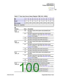
Timer Input Source Select Register
The Timer Input Source Select register, detailed in Table 37, sets the input source for Pro-
grammable Reload Timer 0–3 (TMR0, TMR1, TMR2, TMR3). Event frequency must be
less than one-half of the system clock frequency. When configured for event inputs
through the port pins, the Timers decrement on the fifth system clock rising edge follow-
ing the rising edge of the port pin.
PS013015-0316
Programmable Reload Timers

 ZILOG [ ZILOG, INC. ]