eZ80L92 MCU
Product Specification
89
Real Time Clock Alarm
The clock can be programmed to generate an alarm condition when the current count
matches the alarm set-point registers. Alarm registers are available for seconds, minutes,
hours, and day-of-the-week. Each alarm can be independently enabled. To generate an
alarm condition, the current time must match all enabled alarm values. For example, if the
day-of-the-week and hour alarms are both enabled, the alarm only occurs at the specified
hour on the specified day. The alarm triggers an interrupt if the interrupt enable bit,
INT_EN, is set. The alarm flag, ALARM, and corresponding interrupt to the CPU are
cleared by reading the RTC_CTRL register.
Alarm value registers and alarm control registers can be written at any time. Alarm condi-
tions are generated when the count value matches the alarm value. The comparison of
alarm and count values occurs whenever the RTC count increments (one time every sec-
ond). The RTC can also be forced to perform a comparison at any time by writing a 0 to
RTC_UNLOCK (RTC_UNLOCK is not required to be changed to a 1 first).
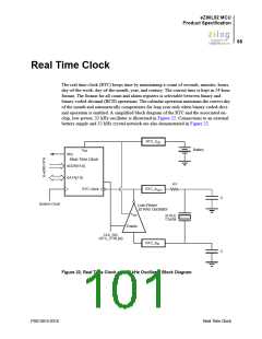
Real Time Clock Oscillator and Source Selection
The RTC count is driven by either an external 32 kHz on-chip oscillator or a 50/60 Hz
power-line frequency input connected to the 32 kHz RTC_XOUT pin. An internal divider
compensates for each of these options. The clock source and power-line frequencies are
selected in the RTC_CTRL register. Writing to the RTC_CTRL register resets the clock
divider.
Real Time Clock Battery Backup
The power supply pin (RTC_VDD) for the RTC and associated low-power 32 kHz
oscillator is isolated from the other power supply pins on the ZLP12840 MCU. To ensure
that the RTC continues to keep time in the event of loss of line power to the application,
a battery can be used to supply power to the RTC and the oscillator via the RTC_VDD pin.
All VSS (ground) pins must be connected together on the printed circuit assembly.
Real Time Clock Recommended Operation
Following a RESET from a powered-down condition, the counter values of the RTC are
undefined and all alarms are disabled. After a RESET from a powered-down condition,
the following procedure is recommended:
•
•
•
•
Write to RTC_CTRL to set RTC_UNLOCK and CLK_SEL.
Write values to the RTC count registers to set the current time.
Write values to the RTC alarm registers to set the appropriate alarm conditions.
Write to RTC_CTRL to clear RTC_UNLOCK; clearing the RTC_UNLOCK bit resets
and enables the clock divider.
PS013015-0316
Real Time Clock Alarm

 ZILOG [ ZILOG, INC. ]