eZ80L92 MCU
Product Specification
102
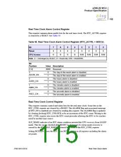
Real Time Clock Alarm Control Register
This register contains alarm enable bits for the real-time clock. The RTC_ACTRL register
is cleared by a RESET. See Table 50.
Table 50. Real Time Clock Alarm Control Register (RTC_ACTRL = 00ECh)
Bit
7
0
6
0
5
0
4
0
3
0
2
0
1
0
0
0
Reset
CPU Access
R
R
R
R
R/W
R/W
R/W
R/W
Note: X = Unchanged by RESET; R = Read-only; R/W = Read/Write.
Bit
Position
Value Description
[7:4]
0000 Reserved.
3
0
1
0
1
0
1
0
1
The day-of-the-week alarm is disabled.
ADOW_EN
The day-of-the-week alarm is enabled.
The hours alarm is disabled.
The hours alarm is enabled.
2
AHRS_EN
1
The minutes alarm is disabled.
The minutes alarm is enabled.
The seconds alarm is disabled.
The seconds alarm is enabled.
AMIN_EN
0
ASEC_EN
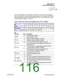
Real-Time Clock Control Register
This register contains control and status bits for the real-time clock. Some bits in the
RTC_CTRL register are cleared by a RESET. The ALARM flag and associated interrupt
(if INT_EN is enabled) are cleared by reading this register. The ALARM flag is updated
by clearing (locking) RTC_UNLOCK or by an increment of the RTC count. Writing to the
RTC_CTRL register also resets the RTC count prescaler allowing the RTC to be synchro-
nized to another time source.
SLP_WAKE indicates if an RTC alarm condition initiated the CPU recovery from SLEEP
mode. This bit can be checked after RESET to determine if a sleep-mode recovery is
caused by the RTC. SLP_WAKE is cleared by a Read of the RTC_CTRL register.
Setting BCD_EN causes the RTC to use BCD counting in all registers including the alarm
set points.
PS013015-0316
Real Time Clock Alarm

 ZILOG [ ZILOG, INC. ]