NJ88C22
2·0
8
7
6
5
4
3
2
1
V
= 5V
DD
V
= 5V
DD
F
= LOW FREQUENCY
IN
OSC IN, F = 0V TO 5V SQUARE WAVE
IN
0V TO 5V SQUARE WAVE
1·5
1·0
0·5
OSC IN
10MHz
1MHz
F
IN
TOTAL SUPPLY CURRENT IS
THE SUM OF THAT DUE TO F
AND OSC IN
IN
1
2
3
4
5
6
7
8
9
10
0·2 0·4
0·6
0·8
1·0
1·2
1·4
1·6
INPUT FREQUENCY (MHz)
INPUT LEVEL (V RMS)
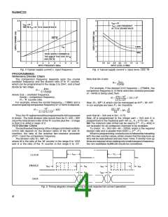
Fig. 3 Typical supply current v. input frequency
Fig. 4 Typical supply current v. input level, OSC IN
PROGRAMMING
Reference Divider Chain
Note that M>A and
The comparison frequency depends upon the crystal
oscillator frequency and the division ratio of th ‘R’ counter,
which can be programmed in the range 3 to 2047, and a fixed
divide by two stage.
fVCO
fcomp
N =
For example, if the desired VCO frequency = 275MHz, the
comparison frequency is 12·5kHz and a two-modulus prescaler
of 464/65 is being used, then
fosc
23fcomp
R =
where fosc = oscillator frequency,
2753106
12·53103
N =
= 223103
fcomp = comparison frequency,
R = ‘R’ counter ratio
For example, where the crystal frequency = 10MHz and a
channelspacingcomparisonfrequencyof12·5kHzisrequired,
Now, N = MP1A, which can be rearranged as N/P = M1A/P.
In our example we have P = 64, therefore
107
2312·53103
223103
A
64
R =
= 400
= M1
64
such that M = 343 and A /64 = 0·75.
Thus,the‘R’registerwouldbeprogrammedto400expressed
in binary. The total division ratio would then be 23400 = 800
since the total division ratio of the ‘R’ counter plus the42 stage
is from 6 to 4094 in steps of 2.
Now, M is programmed to the integer part = 343 and A is
programmed to the fractional part364 i.e., A = 0·75364 = 48.
NB The minimum ratio N that can be used is P 22P (= 4032 in
our example) for all contiguous channels to be available.
To check: N = 343364148 = 22000, which is the required
division ratio and is greater than 4032 ( = P 22P ).
Whenre-programming,aresettozeroisfollowedbyreloading
with the new counter values, which means that the loop lock-up
time will be well defined and less than 10ms. If shorter lock-up
timesarerequired,whenmakingonlysmallchangesinfrequency,
the non-resettable NJ88C28 should be considered.
VCO Divider Chain
Thesynthesisedfrequencyofthevoltagecontrolledoscillator
(VCO) will depend on the division ratios of the ‘M’ and ‘A’
counters, the ratio of the external two-modulus prescaler
(P/P11)and the comparison frequency .
The division ratio N = MP1A,
where M is the ratio of the ‘M’ counter in the range 8 to 1023
and A is the ratio of the ‘A’ counter in the range 0 to 127.
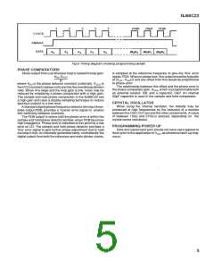
t
t
CL
CH
CLOCK
ENABLE
DATA
t
t
ES
t
t
t
ES
EH
EH
t
DS
DH
Fig. 5 Timing diagram showing timing periods required for correct operation
4

 ZARLINK [ ZARLINK SEMICONDUCTOR INC ]