MVTX2801
Data Sheet
2.1.6 Stop Condition
Generated by the master. The bus is considered to be free after the Stop condition is generated. The Stop condition
occurs if while the SCL line is High, there is a Low-to-High transition of the SDA line.
2
The I C interface serves the function of configuring the MVTX2801 at boot time. The master is the MVTX2801, and
the slave is the EEPROM memory.
2.2 Synchronous Serial Interface
The synchronous serial interface serves the function of configuring the MVTX2801 not at boot time but via a PC. The
PC serves as master and the MVTX2801 serves as slave. The protocol for the synchronous serial interface is nearly
2
identical to the I C protocol. The main difference is that there is no acknowledgment bit after each byte of data
transferred.
The unmanaged MVTX2801 uses a synchronous serial interface to program the internal registers. To reduce the
number of signals required, the register address, command and data are shifted in serially through the PS_DI pin.
PS_STROBE pin is used as the shift clock. PS_DO pin is used as data return path.
Each command consists of four parts.
•
•
•
•
START pulse
Register Address
Read or Write command
Data to be written or read back
Any command can be aborted in the middle by sending an ABORT pulse to the MVTX2801.
A START command is detected when PS_DI is sampled high at PS_STROBE - leading edge, and PS_DI is sampled
low when STROBE- falls.
An ABORT command is detected when PS_DI is sampled low at PS_STROBE - leading edge, and PS_DI is sampled
high when PS_STROBE - falls.
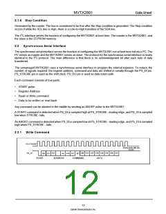
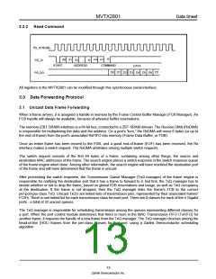
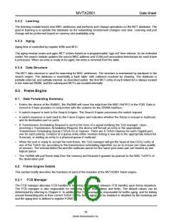
2.2.1 Write Command
PS-STROBE-
2 Extra clocks after last
transfer
A11
PS_DI
A2 ...
ADDRESS
D0 D1 D2 D3 D4 D5 D6 D7
A9
A10
A0 A1
START
W
COMMAND DATA
12
Zarlink Semiconductor Inc.

 ZARLINK [ ZARLINK SEMICONDUCTOR INC ]