MVTX2801
Data Sheet
2.0 System Configuration
The MVTX2801 can be configured by EEPROM (24C02 or compatible) via an I C interface at boot time, or via a
synchronous serial interface during operation.
2
2
2.1 I C Interface
2
The I C interface uses two bus lines, a serial data line (SDA) and a serial clock line (SCL). The SCL line carries the
control signals that facilitate the transfer of information from EEPROM to the switch. Data transfer is 8-bit serial and
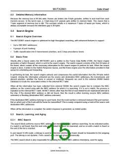
bi-directional, at 50 Kbps. Data transfer is performed between master and slave IC using a request /
acknowledgment style of protocol. The master IC generates the timing signals and terminates data transfer. The
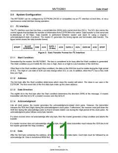
figure below shows the data transfer format.
SLAVE
DATA 1
(8 bits)
START
R/W ACK
ACK
DATA 2
ACK DATA M ACK STOP
ADDRESS
2
Figure 2 - Data Transfer Format for I C Interface
2.1.1 Start Condition
Generated by the master, the MVTX2801. The bus is considered to be busy after the Start condition is generated.
The Start condition occurs if while the SCL line is High, there is a High-to-Low transition of the SDA line.
Other than in the Start condition (and Stop condition), the data on the SDA line must be stable during the High period
2
of SCL. The High or Low state of SDA can only change when SCL is Low. In addition, when the I C bus is free, both
lines are High.
2.1.2 Address
The first byte after the Start condition determines which slave the master will select. The slave in our case is the
EEPROM. The first seven bits of the first data byte make up the slave address.
2.1.3 Data Direction
The eighth bit in the first byte after the Start condition determines the direction (R/W) of the message. A master
transmitter sets this bit to W; a master receiver sets this bit to R.
2.1.4 Acknowledgment
Like all clock pulses, the master generates the acknowledgment-related clock pulse. However, the transmitter
releases the SDA line (High) during the acknowledgment clock pulse. Furthermore, the receiver must pull down the
SDA line during the acknowledge pulse so that it remains stable Low during the High period of this clock pulse. An
acknowledgment pulse follows every byte transfer.
If a slave receiver does not acknowledge after any byte, then the master generates a Stop condition and aborts the
transfer.
If a master receiver does not acknowledge after any byte, then the slave transmitter must release the SDA line to let
the master generate the Stop condition.
2.1.5 Data
After the first byte containing the address, all bytes that follow are data bytes. Each byte must be followed by an
acknowledge bit. Data is transferred MSB-first.
11
Zarlink Semiconductor Inc.

 ZARLINK [ ZARLINK SEMICONDUCTOR INC ]