L9216B/H
Preliminary Data Sheet
September 2001
High-Voltage Ringing SLIC with Ground Start
Example 1, Real Termination
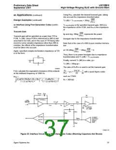
ac Applications (continued)
The following design equations refer to the circuit in
Figure 21. Use these to synthesize real termination
impedance.
Design Examples
First-Generation Codec ac Interface Network—
Resistive Termination
Termination Impedance:
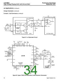
The reference circuit in Figure 22 shows the complete
SLIC schematic for interface to the Agere T7504 first-
generation codec for a resistive termination imped-
ance. For this example, the ac interface was designed
for a 600 Ω resistive termination and hybrid balance
with transmit gain and receive gain set to 0 dBm.
VT/R
–IT/R
------------
zT =
2400
zT = 50 Ω + 2RP +
----------------------------------
RT1
RT1
1 +
+
-------- -----------
RGP RRCV
This is a lower feature application example and uses
single battery operation, fixed overhead, current limit,
and loop closure threshold.
Resistor RGN is optional. It compensates for any mis-
match of input bias voltage at the RCVN/RCVP inputs.
If it is not used, there may be a slight offset at tip and
ring due to mismatch of input bias voltage at the
RCVN/RCVP inputs. It is very common to simply tie
RCVN directly to ground in this particular mode of oper-
ation. If used, to calculate RGN, the impedance from
RCVN to ac ground should equal the impedance from
RCVP to ac ground.
Receive Gain:
VT/R
-----------
grcv =
VFR
8
grcv =
------------------------------------------------------------------
RRCV RRCV
ZT
1 +
+
1 +
--------
----------- -----------
RT1
RGP
ZT/R
Transmit Gain:
VGSX
----------
gtx =
VT/R
–RX 300
-------- --------
gtx =
×
RT2
ZT/R
Hybrid Balance:
hbal = 20log
RX
RHB
-----------
– gtx × grcv
VGSX
--------------
hbal = 20log
VFR
To optimize the hybrid balance, the sum of the currents
at the VFX input of the codec op amp should be set to
0. The expression for ZHB becomes the following:
RX
-------------------
RHB(kΩ) =
gtx × grcv
Agere Systems Inc.
33

 ZARLINK [ ZARLINK SEMICONDUCTOR INC ]