R
XCR3064A: 64 Macrocell CPLD With Enhanced Clocking
Switching Characteristics
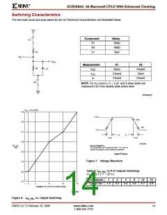
The test load circuit and load values for the AC Electrical Characteristics are illustrated below.
V
CC
Component
Values
390Ω
390Ω
35pF
S1
R1
R2
C1
R1
R2
V
IN
V
OUT
Measurement
S1
S2
C1
t
Open
Closed
Open
PZH
t
Closed
Closed
PZL
t
P
Closed
S2
NOTE: For tPHZ and tPLZ C = 5 pF, and 3-state levels are
measured 0.5V from steady-state active level.
SP00461B
V
= 3.3 V, 25°C
CC
5.9
+3.0V
90%
5.8
5.7
5.6
5.5
5.4
10%
0V
t
t
F
R
1.5ns
1.5ns
SP00368
t
PD_PAL
(ns)
MEASUREMENTS:
All circuit delays are measured at the +1.5V level of
inputs and outputs, unless otherwise specified.
Input Pulses
Figure 7: Voltage Waveform
Table 6: t
vs # of Outputs Switching
5.3
5.2
PD_PAL
(V = 3.3 V, T = 25°C)
CC
# of Outputs
1
2
4
8
12
16
1
2
4
8
12
16
Typical (ns)
5.3
5.3
5.4
5.6
5.7
5.9
NUMBER OF OUTPUTS SWITCHING
SP00639
Figure 6:
t
vs. Output Switching
PD_PAL
DS037 (v1.1) February 10, 2000
www.xilinx.com
1-800-255-7778
14

 XILINX [ XILINX, INC ]