Spartan-3E FPGA Family: Functional Description
Table 65: Slave Parallel Mode Connections (Cont’d)
Pin Name
FPGA Direction
Description
During Configuration
After Configuration
INIT_B
Open-drain
bidirectional I/O Goes Low at the start of
Initialization Indicator. Active Low. Active during configuration. If
User I/O. If unused in the
application, drive INIT_B
High.
CRC error detected during
configuration during the Initialization configuration, FPGA drives
memory clearing process. Released INIT_B Low.
at the end of memory clearing, when
mode select pins are sampled. In
daisy-chain applications, this signal
requires an external 4.7 kΩ pull-up
resistor to VCCO_2.
DONE
Open-drain
FPGA Configuration Done. Low
Low indicates that the FPGA is not Pulled High via external
bidirectional I/O during configuration. Goes High
when FPGA successfully completes
configuration. Requires external 330
Ω pull-up resistor to 2.5V.
yet configured.
pull-up. When High,
indicates that the FPGA
successfully configured.
PROG_B
Input
Program FPGA. Active Low. When Must be High to allow
Drive PROG_B Low and
release to reprogram
FPGA.
asserted Low for 500 ns or longer,
forces the FPGA to restart its
configuration process by clearing
configuration memory and resetting
the DONE and INIT_B pins once
PROG_B returns High. Recommend
external 4.7 kΩ pull-up resistor to
2.5V. Internal pull-up value may be
weaker (see Table 78). If driving
externally with a 3.3V output, use an
open-drain or open-collector driver
or use a current limiting series
resistor.
configuration to start.
Voltage Compatibility
V
Most Slave Parallel interface signals are within the
FPGA’s I/O Bank 2, supplied by the VCCO_2 supply input.
The VCCO_2 voltage can be 1.8V, 2.5V, or 3.3V to match
the requirements of the external host, ideally 2.5V. Using
1.8V or 3.3V requires additional design considerations as
the DONE and PROG_B pins are powered by the FPGA’s
2.5V V
supply. See XAPP453: The 3.3V
CCAUX
Configuration of Spartan-3 FPGAs for additional
information.
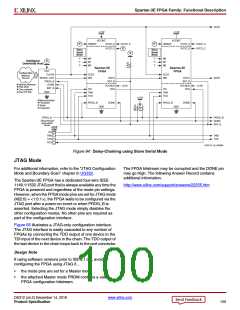
Daisy-Chaining
If the application requires multiple FPGAs with different
configurations, then configure the FPGAs using a daisy
chain. Use Slave Parallel mode (M[2:0] = <1:1:0>) for all
FPGAs in the daisy-chain. The schematic in Figure 62 is
optimized for FPGA downloading and does not support the
SelectMAP read interface. The FPGA’s RDWR_B pin must
be Low during configuration.
After the lead FPGA is filled with its configuration data, the
lead FPGA enables the next FPGA in the daisy-chain by
asserting is chip-select output, CSO_B.
DS312 (v4.2) December 14, 2018
www.xilinx.com
Product Specification
96

 XILINX [ XILINX, INC ]