Philips Semiconductors
Preliminary specification
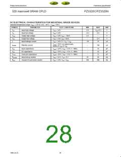
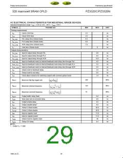
320 macrocell SRAM CPLD
PZ3320C/PZ3320N
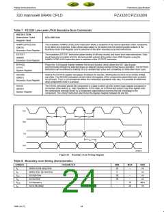
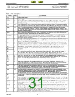
Table 9. Pin Description
SYMBOL
TYPE
DESCRIPTION
V
–
–
I
Positive power supply.
Ground supply.
DD
GND
resetn
During configuration, resetn forces the start of initialization (see Figure 8). After configuration, resetn is a direct
input which can be used to asynchronously reset all the flip-flops. If the global reset is not being used, this pin
should be pulled high.
cclk
I/O
I/O
In the master modes, cclk is an output which strobes configuration data in. In the slave or synchronous peripheral
mode, cclk is an input synchronous with the data on din or D[7:0]. After configuration, this pin should be pulled low.
done
done is a bi-directional signal with a weak pull-up resistor attached. As an output, done pulling high indicates
configuration is complete. As an input, a low level on done will delay device initialization and the enabling of user
I/O. If only one device is used, this pin can be left floating. If multiple devices are daisy chained, an external pull-up
should be used (see Figure 28).
pgmn
I
pgmn is an active-low input that forces the restart of configuration and initialization (see Figure 8) and resets the
boundary-scan circuitry. After configuration, the pin should be pulled high.
rdy_busyn
O
During configuration in peripheral mode, rdy_busyn indicates another byte can be written to the PZ3320. After
configuration, the pin is a user-programmable I/O, and no external termination is required. See the section on
terminations for more information.
rclk
din
O
I
During the master parallel configuration mode, rclk is an output signal to an external memory. rclk is not normally
used. After configuration, this pin is a user-programmable I/O pin, and no external termination is required. See the
section on terminations for more information.
During slave serial or master serial configuration modes, din accepts serial configuration data synchronous with
cclk. During parallel configuration modes, din is the D[0] input. After configuration, the pin is a user-programmable
I/O, and no external termination is required. See the section on terminations for more information.
M2
M0
M1
M3
I
M2/M1/M0 are used to select the configuration mode as defined in Table 3. After configuration, the pins are
user-programmable I/O, and no external termination is required. See the section on terminations for more
information.
I
M3 is used to select the frequency of the internal oscillator during configuration. When M3 is low, the oscillator is
nominally 10MHz. When M3 is high, the oscillator is nominally 1.25MHz. After configuration, the pin is a
user-programmable I/O, and no external termination is required. See the section on terminations for more information.
tdi
tdo
tck
I
O
I
Test Data In, Test Data Out, Test Clock, Test Mode Select, Test Reset are dedicated pins for boundary-scan
through the JTAG port. If JTAG is not being used, tdi, tck, tms, and trstn should be terminated with a weak pull-up
resistor. tdo can be left unterminated. See section on terminations for more information.
tms
trstn
I
I
hdc
ldcn
initn
O
High During Configuration (hdc) is output high when the PZ3320 is in the configuration state. hdc is used as a
control output indicating that configuration is in progress. After configuration, the pin is a user-programmable I/O,
and no external termination is required. See the section on terminations for more information.
O
Low During Configuration (ldcn) is output low when the PZ3320 is in the configuration state. ldcn is used as a
control output indicating that configuration is in progress. After configuration, the pin is a user-programmable I/O,
and no external termination is required. See the section on terminations for more information.
I/O
initn is an active-low bi-directional pin that holds the PZ3320 in a wait state before the start of configuration. During
configuration, an internal pull-up is enabled. If only one device is used, this pin can be left floating. If multiple devices
are daisy chained, an external pull-up should be used (see Figure 28). After configuration, the pin is a
user-programmable I/O, and no external termination is required. See the section on terminations for more information.
gts
I
I
Global 3-State is an active-high dedicated input used to 3-state the I/Os. If this feature is not used, the pin should
be pulled low.
cs0n
cs1
cs0n/cs1 are used in the peripheral configuration mode. The PZ3320 is selected when cs0n is low and cs1 is high.
After configuration, these pins are user-programmable I/O, and no external termination is required. See the section
on terminations for more information.
A[19:0]
D[7:0]
dout
O
I
In the master parallel configuration mode, A[19:0] address the configuration EEPROM. After configuration, the pin
is a user-programmable I/O, and no external termination is required. See the section on terminations for more
information.
During master parallel, peripheral, and slave parallel configuration modes, D[7:0] receive configuration data. After
configuration, the pin is a user-programmable I/O, and no external termination is required. See the section on
terminations for more information.
O
During configuration, dout is the serial data out that is used to drive the din of daisy-chained slave devices. Data on
dout changes on the falling edge of cclk. After configuration, the pin is a user-programmable I/O, and no external
termination is required. See the section on terminations for more information.
31
1998 Jul 22

 XILINX [ XILINX, INC ]