R
Functional Description
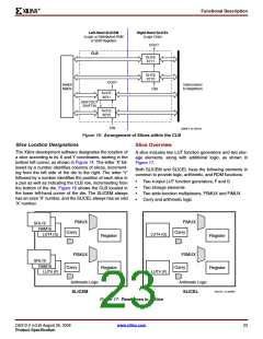
Left-Hand SLICEM
(Logic or Distributed RAM
or Shift Register)
Right-Hand SLICEL
(Logic Only)
COUT
CLB
SLICE
X1Y1
SLICE
X1Y0
COUT
Switch
Matrix
Interconnect
to Neighbors
CIN
SLICE
X0Y1
SHIFTOUT
SHIFTIN
SLICE
X0Y0
CIN
DS099-2_05_082104
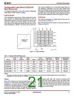
Figure 16: Arrangement of Slices within the CLB
Slice Location Designations
Slice Overview
The Xilinx development software designates the location of
a slice according to its X and Y coordinates, starting in the
bottom left corner, as shown in Figure 14. The letter ‘X’ fol-
lowed by a number identifies columns of slices, increment-
ing from the left side of the die to the right. The letter ‘Y’
followed by a number identifies the position of each slice in
a pair as well as indicating the CLB row, incrementing from
the bottom of the die. Figure 16 shows the CLB located in
the lower left-hand corner of the die. The SLICEM always
has an even ‘X’ number, and the SLICEL always has an odd
‘X’ number.
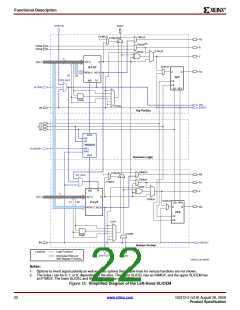
A slice includes two LUT function generators and two stor-
age elements, along with additional logic, as shown in
Figure 17.
Both SLICEM and SLICEL have the following elements in
common to provide logic, arithmetic, and ROM functions:
•
•
•
•
Two 4-input LUT function generators, F and G
Two storage elements
Two wide-function multiplexers, F5MUX and FiMUX
Carry and arithmetic logic
FiMUX
SRL16
FiMUX
RAM16
Carry
Carry
LUT4 (G)
LUT4 (G)
Register
Register
F5MUX
F5MUX
SRL16
RAM16
Carry
Carry
Register
Register
LUT4 (F)
LUT4 (F)
Arithmetic Logic
Arithmetic Logic
DS312-2_13_020905
SLICEM
SLICEL
Figure 17: Resources in a Slice
DS312-2 (v3.8) August 26, 2009
www.xilinx.com
23
Product Specification

 XILINX [ XILINX, INC ]