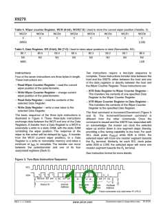
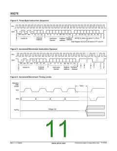
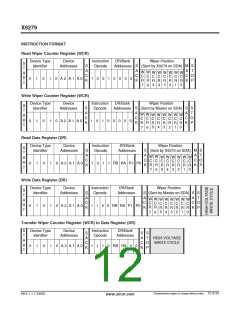
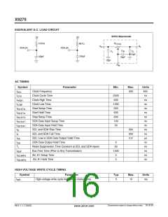
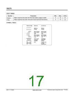
X9279
ABSOLUTE MAXIMUM RATINGS
COMMENT
Temperature under bias ....................–65°C to +135°C
Storage temperature .........................–65°C to +150°C
Voltage on SCL, SDA any address input
Stresses above those listed under “Absolute Maximum
Ratings” may cause permanent damage to the device.
This is a stress rating only; the functional operation of
the device (at these or any other conditions above
those listed in the operational sections of this
specification) is not implied. Exposure to absolute
maximum rating conditions for extended periods may
affect device reliability.
with respect to V ..................................–1V to +7V
SS
∆V = | (V –V ) |.................................................... 5.5V
H
L
Lead temperature (soldering, 10 seconds)........ 300°C
I
(10 seconds).................................................. 6mA
W
RECOMMENDED OPERATING CONDITIONS
Device
X9279
Supply Voltage (V
)
(4) Limits
Temp
Commercial
Industrial
Min.
0°C
Max.
+70°C
+85°C
CC
5V 10%
X9279-2.7
2.7V to 5.5V
–40°C
ANALOG CHARACTERISTICS (Over recommended industrial (2.7V) operating conditions unless otherwise stated.)
Limits
Symbol
Parameter
End to End Resistance
End to End Resistance
End to End Resistance Tolerance
Power Rating
Min.
Typ.
100
50
Max.
Units
kΩ
kΩ
%
Test Conditions
T version
R
TOTAL
R
U version
TOTAL
20
50
mW
mA
Ω
25°C, each pot
I
Wiper Current
3
W
R
R
Wiper Resistance
300
150
I
I
=
=
3mA @ V = 3V
CC
W
W
Wiper Resistance
Ω
3mA @ V = 5V
CC
W
W
V
Voltage on any R or R Pin
V
V
V
V
= 0V
TERM
H
L
SS
CC
SS
Noise
-120
0.4
dBV/ Hz Ref: 1V
Resolution
%
(5)
Absolute Linearity (1)
1
MI(3)
R
– R
w(n)(actual)
w(n)(expected)
(5)
Relative Linearity (2)
0.2
20
MI(3)
R
– [R
]
w(n + 1)
w(n) + MI
Temperature Coefficient of
300
ppm/°C
R
TOTAL
Ratiometric Temp. Coefficient
Potentiometer Capacitances
ppm/°C
pF
C /C /C
W
10/10/25
See Macro model
H
L
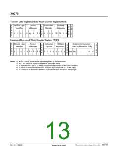
Notes: (1) Absolute linearity is utilized to determine actual wiper voltage versus expected voltage as determined by wiper position when used
as a potentiometer.
(2) Relative linearity is utilized to determine the actual change in voltage between two successive tap positions when used as a
potentiometer. It is a measure of the error in step size.
(3) MI = RTOT / 255 or (R – R ) / 255, single pot
H
L
(4) During power up V > V , V , and V .
CC
H
L
W
(5) n = 0, 1, 2, ....,255; m =0, 1, 2, ...., 254.
Characteristics subject to change without notice. 14 of 24
REV 1.1.7 2/6/03
www.xicor.com

 XICOR [ XICOR INC. ]