WM8983
Product Preview
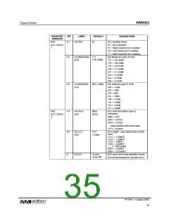
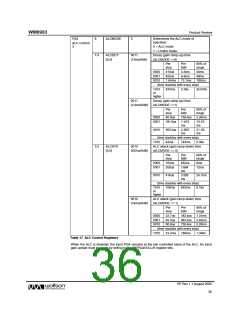
Determines the ALC mode of
R34
8
ALCMODE
0
operation:
ALC Control
3
0 = ALC mode
1 = Limiter mode.
Decay (gain ramp-up) time
(ALCMODE ==0)
7:4
ALCDCY
[3:0]
0011
(13ms/6dB)
Per
step
Per
6dB
90% of
range
0000
0001
0010
410us
820us
1.64ms
3.3ms
6.6ms
13.1ms
24ms
48ms
192ms
… (time doubles with every step)
1010
or
420ms
3.36s
24.576s
higher
0011
Decay (gain ramp-up) time
(ALCMODE ==1)
(2.9ms/6dB)
Per
step
Per
6dB
90% of
range
0000
0001
90.8us
726.4us 5.26ms
181.6us 1.453
ms
10.53
ms
0010
363.2us 2.905
ms
21.06
ms
… (time doubles with every step)
1010 93ms 744ms 5.39s
3:0
ALCATK
[3:0]
0010
ALC attack (gain ramp-down) time
(ALCMODE == 0)
(832us/6dB)
Per
step
Per
6dB
90% of
range
0000
0001
104us
208us
832us
6ms
1.664
ms
12ms
0010
416us
3.328
ms
24.1ms
… (time doubles with every step)
1010
or
106ms
852ms
6.18s
higher
0010
ALC attack (gain ramp-down) time
(ALCMODE == 1)
(182us/6dB)
Per
step
Per
6dB
90% of
range
0000
0001
0010
22.7us
45.4us
90.8us
182.4us 1.31ms
363.2us 2.62ms
726.4us 5.26ms
… (time doubles with every step)
1010 23.2ms 186ms 1.348s
Table 17 ALC Control Registers
When the ALC is disabled, the input PGA remains at the last controlled value of the ALC. An input
gain update must be made by writing to the INPPGAVOLL/R register bits.
PP Rev 1.1 August 2005
36
w

 WOLFSON [ WOLFSON MICROELECTRONICS PLC ]