WM8983
Product Preview
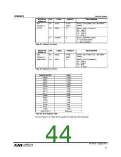
REGISTER
ADDRESS
BIT
LABEL
DEFAULT
DESCRIPTION
R11
7:0
DACLVOL
[7:0]
11111111
( 0dB )
Left DAC Digital Volume Control
0000 0000 = Digital Mute
0000 0001 = -127dB
Left DAC
Digital Volume
0000 0010 = -126.5dB
... 0.5dB steps up to
1111 1111 = 0dB
8
DACVU
Not
latched
DAC left and DAC right volume do
not update until a 1 is written to
DACVU (in reg 11 or 12)
R12
7:0
DACRVOL
[7:0]
11111111
( 0dB )
Right DAC Digital Volume Control
0000 0000 = Digital Mute
0000 0001 = -127dB
Right DAC
Digital Volume
0000 0010 = -126.5dB
... 0.5dB steps up to
1111 1111 = 0dB
8
DACVU
Not
latched
DAC left and DAC right volume do
not update until a 1 is written to
DACVU (in reg 11 or 12)
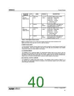
Table 21 DAC Digital Volume Control
Note: An additional gain of up to 12dB can be added using the gain block embedded in the
digital peak limiter circuit (see DAC OUTPUT LIMITER section).
5-BAND EQUALISER
A 5-band graphic equaliser function which can be used to change the output frequency levels to suit
the environment. This can be applied to the ADC or DAC path and is described in the 5-BAND
EQUALISER section for further details on this feature.
3-D ENHANCEMENT
The WM8983 has an advanced digital 3-D enhancement feature which can be used to vary the
perceived stereo separation of the left and right channels. Like the 5-band equaliser this feature can
be applied to either the ADC record path or the DAC plaback path but not both simultaneously.
Refer to the 3-D STEREO ENHANCEMENT section for further details on this feature.
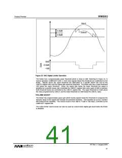
DAC DIGITAL OUTPUT LIMITER
The WM8983 has a digital output limiter function. The operation of this is shown in Figure 22. In
this diagram the upper graph shows the envelope of the input/output signals and the lower graph
shows the gain characteristic.
PP Rev 1.1 August 2005
40
w

 WOLFSON [ WOLFSON MICROELECTRONICS PLC ]