WM8959
Pre-Production
Details of the GPIO implementation are shown below. In order to avoid GPIO loops if a GPIO is
configured as an output the corresponding input is disabled, as shown in Figure 44 below.
Figure 44 GPIO Pad
The GPIO register, i.e. latch structure, is shown in Figure 45 below. The de-bounce Control fields
GPIOn_DEB_ENA determine whether the signal is de-bounced or not. (Note that TOCLK (via
SYSCLK) needs to be present in order for the debounce circuit to work.) The polarity bits
GPIO_POL[7:0] control whether an interrupt is triggered by a logic 1 level (for GPIO_POL[n] = 0) or a
logic 0 level (for GPIO_POL[n] = 1). The latch will cause the interrupt to be stored until it is reset by
writing to the Interrupt Register. The latched signal is processed by the IRQ circuit, shown in Figure
43 above. The interrupt status bits can be read at any time from Register R18 (see Table 47) and are
reset by writing a “1” to the applicable bit in Register R18.
Note that the interrupt behaviour is driven by level detection (not edge detection). Therefore, if an
input remains asserted after the interrupt register has been reset, then the interrupt event will be
triggered again even though no transition has occurred. If edge detection is required, this may be
implemented as described in the following paragraphs.
Figure 45 GPIO Function
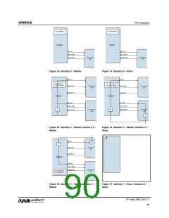
Three typical scenarios are presented in the following Figure 46, Figure 47 and Figure 48. The
examples are:
•
•
•
Latch a GPIO input (Figure 46)
Debounce and latch a GPIO input (Figure 47)
Use the GPIOn_POL bit to implement an IRQ edge detect function (Figure 48)
PP, May 2008, Rev 3.1
86
w

 WOLFSON [ WOLFSON MICROELECTRONICS PLC ]