Pre-Production
WM8959
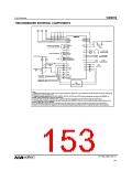
RECOMMENDED EXTERNAL COMPONENTS
DVDD
Vbatt
AVDD
0.1
F
0.1
F
4.7
F
4.7
F
4.7 F
WM8959
AVDD
AGND
HPGND
SPKGND
DGND
HPVDD
SPKVDD
DCVDD
DBVDD
MICBIAS
4.7
F
4.7 F
MODE
CSB/ADDR
SCLK
MICBIAS
VMID
CONTROL INTERFACE
(2, 3 or 4-wire via GPIO)
AGND
SDIN
MCLK
LOUT
ROUT
16 or 32 OHM
HEADPHONES
220
220
F
F
BCLK
DACLRC
DACDAT
AUDIO INTERFACE
OUT3
OUT4
16 or 32 OHM
EAR SPEAKER
MICBIAS
GPIO1
GPIO3/BCLK2
GPIO4/DACLRC2
GPIO5/DACDAT2
GPIO
2k2
2k2
SPKP
SPKN
8 OHM
LOUDSPEAKER
LIN1
1
F
HEADSET
MIC
ROP
RON
LOP
LON
LINE
OUTPUTS
1
F
F
F
F
LIN2
1
1
1
F
F
F
1
1
1
LIN3/GPI7
LIN4/RXN
HANDSET
MIC
RIN1
1
1
1
1
F
F
F
F
RIN2
LINE INPUT
(FM Radio)
RIN3/GPI8
RIN4/RXP
LINE INPUT
(Melody Chip)
BB
(Voice CODEC)
Notes:
1. Wolfson recommends using a single, common ground reference. Where this is not possible care should be taken to optimise split ground
configuration for audio performance.
2. Supply decoupling capacitors on DCVDD, DBVDD, SPKVDD, HPVDD and AVDD should be positioned as close to the WM8959 as
possible. Values indicated are minimum requirements.
3. Capacitor types should be carefully chosen. Capacitors with very low ESR are recommended for optimum performance.
4. The loudspeaker should be connected as close as possible to the WM8959. When this is not possible, filtering should be placed on the
speaker outputs close to the WM8959.
5. The 2k2 MICBIAS resistors on each of the MIC inputs are typical values and will be suitable for many electret type microphones.
However, it is recommended that engineers refer to individual microphone specifications prior to finalising the value of this component.
PP, May 2008, Rev 3.1
w
153

 WOLFSON [ WOLFSON MICROELECTRONICS PLC ]