Pre-Production
WM8959
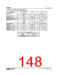
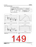
DAC FILTER RESPONSES
DAC STOPBAND ATTENUATION
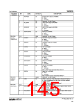
The DAC digital filter type is selected by the DAC_SB_FILT register bit as shown in Table 82.
REGISTER
ADDRESS
BIT
LABEL
DEFAULT
DESCRIPTION
R10 (0Ah)
8
DAC_SB_FI
LT
0b
Selects DAC filter characteristics
0 = Normal mode
1 = Sloping stopband mode
Table 82 DAC Filter Selection
MAGNITUDE(dB)
MAGNITUDE(dB)
10
-10
0.04
0.035
0.03
0
0.5
1
1.5
2
2.5
3
-30
0.025
0.02
-50
-70
0.015
0.01
-90
-110
-130
-150
0.005
0
0
0.05
0.1
0.15
0.2
0.25
0.3
0.35
0.4
0.45
0.5
-0.005
Frequency (fs)
Frequency (fs)
Figure 87 DAC Digital Filter Frequency Response (Normal
Mode)
Figure 88 DAC Digital Filter Ripple (Normal Mode)
MAGNITUDE(dB)
MAGNITUDE(dB)
10
0.05
0
-10
-30
0
0.5
1
1.5
2
2.5
3
0
0.05
0.1
0.15
0.2
0.25
0.3
0.35
0.4
0.45
0.5
-0.05
-0.1
-0.15
-0.2
-50
-70
-0.25
-0.3
-90
-0.35
-0.4
-110
-130
-150
-0.45
-0.5
Frequency (fs)
Frequency (fs)
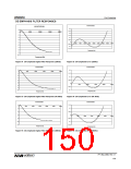
Figure 89 DAC Digital Filter Frequency Response (Sloping
Stopband Mode)
Figure 90 DAC Digital Filter Ripple (Sloping Stopband
Mode)
PP, May 2008, Rev 3.1
149
w

 WOLFSON [ WOLFSON MICROELECTRONICS PLC ]