WM8352
Production Data
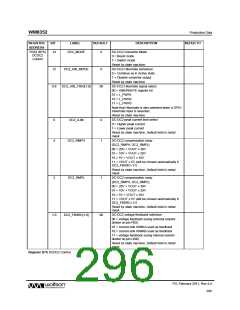
REFER TO
REGISTER
ADDRESS
BIT
LABEL
DEFAULT
DESCRIPTION
Reset by state machine. Default held in metal mask.
DCDC3 converter enable
0 = disabled
2
DC3_ENA
0
1 = enabled
Note: internal conditions may prevent the converter
from actually switching on - see DCDC/LDO Status
register for actual converter status.
Reset by state machine. Default held in metal mask.
DCDC2 converter enable
0 = disabled
1
0
DC2_ENA
DC1_ENA
0
0
1 = enabled
Note: internal conditions may prevent the converter
from actually switching on - see DCDC/LDO Status
register for actual converter status.
Reset by state machine. Default held in metal mask.
DCDC1 converter enable
0 = disabled
1 = enabled
Note: internal conditions may prevent the converter
from actually switching on - see DCDC/LDO Status
register for actual converter status.
Reset by state machine. Default held in metal mask.
Register B0h DCDC/LDO requested
REGISTER
ADDRESS
BIT
LABEL
DEFAULT
DESCRIPTION
REFER TO
R177 (B1h)
DCDC
Active
15
DCDC_DISCLKS
0
DCDC clock enable
0 = DCDC Clocks enabled
1 = DCDC1, 3, 4 and 6 clocks disabled.
options
Note: This feature is useful in reducing the current
consumption if all 4 DCDCs are in LDO mode. The
requirement is to put them in LDO mode and then at
least 100us is required before clocks are disabled.
Again while coming out of LDO mode first enable the
clocks and then at least 100us wait and then come
out of LDO mode. This can only be used if the
processor is alive to set and unset this bit.
Reset by state machine.
Power up time out value for all converters
00 = 0.5ms
13:12
PUTO[1:0]
00
01 = 2ms
10 = 32ms
11 = 256ms
Reset by state machine.
DC-DC 6 Active mode
0 = Select Standby mode
1 = Select Active mode
Reset by state machine.
DC-DC 4 Active mode
0 = Select Standby mode
1 = Select Active mode
Reset by state machine.
DC-DC 3 Active mode
0 = Select Standby mode
1 = Select Active mode
5
3
2
DC6_ACTIVE
DC4_ACTIVE
DC3_ACTIVE
1
1
1
PD, February 2011, Rev 4.4
292
w

 WOLFSON [ WOLFSON MICROELECTRONICS PLC ]