Production Data
WM8352
REGISTER
ADDRESS
BIT
LABEL
DEFAULT
DESCRIPTION
REFER TO
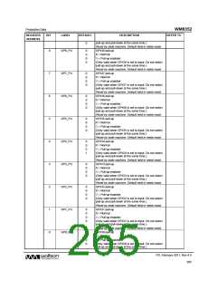
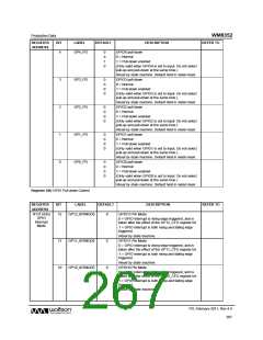
4
GP4_PD
0
0
1
0
GPIO4 pull-down
0 = Normal
1 = Pull-down enabled
(Only valid when GPIO4 is set to input. Do not select
pull-up and pull-down at the same time.)
Reset by state machine. Default held in metal mask.
GPIO3 pull-down
3
2
1
0
GP3_PD
GP2_PD
GP1_PD
GP0_PD
0
0
0
0
0 = Normal
1 = Pull-down enabled
(Only valid when GPIO3 is set to input. Do not select
pull-up and pull-down at the same time.)
Reset by state machine. Default held in metal mask.
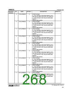
GPIO2 pull-down
0
0
0
0
0 = Normal
1 = Pull-down enabled
(Only valid when GPIO2 is set to input. Do not select
pull-up and pull-down at the same time.)
Reset by state machine. Default held in metal mask.
GPIO1 pull-down
0
0
0
0
0 = Normal
1 = Pull-down enabled
(Only valid when GPIO1 is set to input. Do not select
pull-up and pull-down at the same time.)
Reset by state machine. Default held in metal mask.
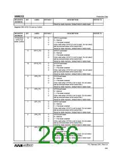
GPIO0 pull-down
0
0
0
0
0 = Normal
1 = Pull-down enabled
(Only valid when GPIO0 is set to input. Do not select
pull-up and pull-down at the same time.)
Reset by state machine. Default held in metal mask.
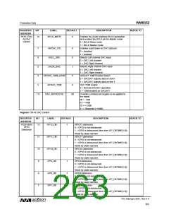
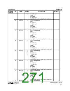
Register 82h GPIO Pull down Control
REGISTER
ADDRESS
BIT
LABEL
DEFAULT
DESCRIPTION
REFER TO
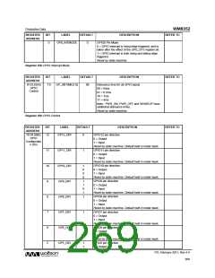
R131 (83h)
GPIO
Interrupt
Mode
12
GP12_INTMODE
0
GPIO12 Pin Mode
0 = GPIO interrupt is rising edge triggered, and is
taken after the effect of the GP12_CFG register bit.
1 = GPIO interrupt is both rising and falling edge
triggered.
Reset by state machine.
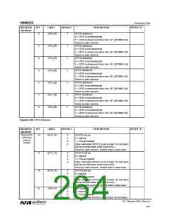
11
10
GP11_INTMODE
GP10_INTMODE
0
0
GPIO11 Pin Mode
0 = GPIO interrupt is rising edge triggered, and is
taken after the effect of the GP11_CFG register bit.
1 = GPIO interrupt is both rising and falling edge
triggered.
Reset by state machine.
GPIO10 Pin Mode
0 = GPIO interrupt is rising edge triggered, and is
taken after the effect of the GP10_CFG register bit.
1 = GPIO interrupt is both rising and falling edge
triggered.
Reset by state machine.
PD, February 2011, Rev 4.4
267
w

 WOLFSON [ WOLFSON MICROELECTRONICS PLC ]