WM8352
Production Data
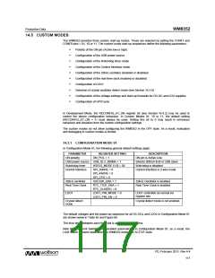
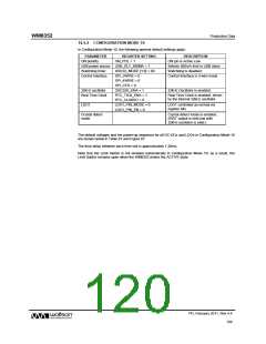
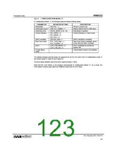
14.5.2 CONFIGURATION MODE 10
In Configuration Mode 10, the following general default settings apply:
PARAMETER
REGISTER SETTING
ON_POL = 1
DESCRIPTION
ON pin is Active Low
ON polarity
USB power source USB_SLV_500MA = 1
Selects 500mA limit in USB slave
Watchdog is disabled
Watchdog timer
Control Interface
WDOG_MODE [1:0] = 00
SPI_3WIRE = 0
Control Interface is 2-wire mode
SPI_4WIRE = 0
SPI_CFG = 0
32kHz oscillator
Real Time Clock
OSC32K_ENA = 1
RTC_TICK_ENA = 1
RTC_CLKSRC = 0
LDO1_PIN_MODE = 0
LDO1_PIN_EN = 0
32kHz Oscillator is enabled
Real Time Clock is enabled, driven
by the internal 32kHz oscillator
LDO1
LDO1 controlled as normal via
register bits
Crystal detect
mode
Crystal detect mode is enabled.
(/RST output is held low until
32kHz oscillator is valid.)
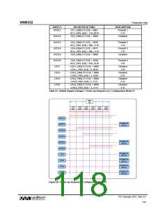
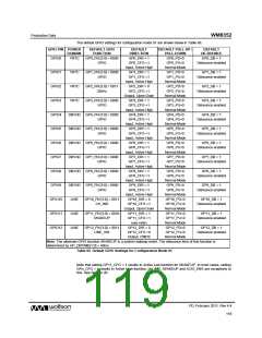
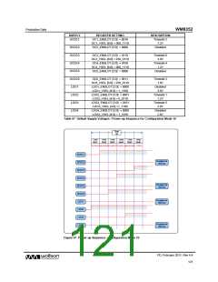
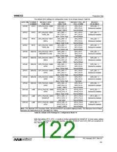
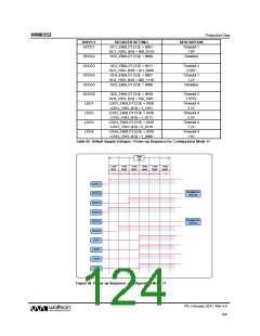
The default voltages and the power-up sequence for all DC-DCs and LDOs in Configuration Mode 10
are shown below in Table 67 and Figure 67.
The time delay between each time slot is approximately 1.28ms.
Note that the Limit Switch is not enabled automatically in Configuration Mode 10; as a result, the
Limit Switch remains open when the WM8352 enters the ACTIVE state.
PD, February 2011, Rev 4.4
120
w

 WOLFSON [ WOLFSON MICROELECTRONICS PLC ]