W83697HF/F
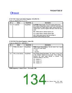
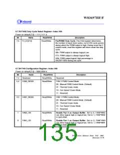
9.7.53 FAN2 Duty Cycle Select Register-- Index 03h
Power on default [7:0] = 1111,1111 b
Bit
Name
F2_DC[7:0]
Read/Write
Description
7-0
Read/Write
FanPWM2 Duty Cycle. This 8-bit register determines
the number of input clock cycles, out of 256-cycle period,
during which the PWM output is high. During smart fan 2
control mode, read this register will return smart fan duty
cycle.
00h: PWM output is always logical Low.
FFh: PWM output is always logical High.
XXh: PWM output logical High percentage is
XX/256*100% during one cycle.
9.7.54 FAN Configuration Register-- Index 04h
Power on default [7:0] = 0000,0000 b
Bit
7-2
5-4
Name
Reserved
Read/Write
Read/Write
Read/Write
Description
Reserved
FAN2_MODE
FAN 2 PWM Control Mode.
00 - Manual PWM Control Mode. (Default)
01 - Thermal Cruise mode.
10 - Fan Speed Cruise Mode.
11 - Reserved.
3-2
FAN1_MODE
Read/Write
FAN 1 PWM Control Mode.
00 - Manual PWM Control Mode. (Default)
01 - Thermal Cruise mode.
10 - Fan Speed Cruise Mode.
11 - Reserved.
1
0
FAN2_OB
FAN1_OB
Read/Write
Read/Write
Enable Fan 2 as Output Buffer. Set to 0, FANPWM2
can drive logical high or logical low. Set to 1, FANPWM2
is open-drain
Enable Fan 1 as Output Buffer. Set to 0, FANPWM1
can drive logical high or logical low. Set to 1, FANPWM1
is open-drain
Publication Release Date: Feb. 2002
- 126 -
Revision 0.70

 WINBOND [ WINBOND ]