Preliminary W78E51B
3. Reduce EMI Emission
Because of on-chip MTP-ROM, when a program is running in internal ROM space, the ALE will be
unused. The transition of ALE will cause noise, so it can be turned off to reduce the EMI emission if it
is useless. Turning off the ALE signal transition only requires setting the bit 0 of the AUXR SFR,
which is located at 08Eh. When ALE is turned off, it will be reactivated when the program accesses
external ROM/RAM data or jumps to execute an external ROM code. The ALE signal will turn off
again after it has been completely accessed or the program returns to internal ROM code space. The
AO bit in the AUXR register, when set, disables the ALE output. In order to reduce EMI emission from
oscillation circuitry, W78E51B allows user to diminish the gain of on-chip oscillator amplifiers by using
programmer to clear the B7 bit of security register. Once B7 is set to 0, a half of gain will be
decreased. Care must be taken if user attempts to diminish the gain of oscillator amplifier, reducing a
half of gain may effect to external crystal operating improperly at high frequency above 24MHz. The
value of R and C1,C2 may need adjustment while running at lower gain.
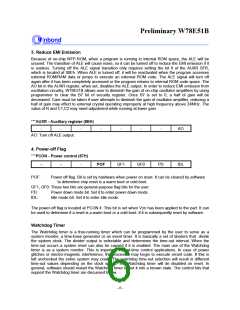
***AUXR - Auxiliary register (8EH)
-
-
-
-
-
-
-
AO
AO: Turn off ALE output.
4. Power-off Flag
***PCON - Power control (87H)
-
GF1
GF0
PD
IDL
-
-
POF
POF:
Power off flag. Bit is set by hardware when power on reset. It can be cleared by software
to determine chip reset is a warm boot or cold boot.
GF1, GF0: These two bits are general-purpose flag bits for the user.
PD:
IDL:
Power down mode bit. Set it to enter power down mode.
Idle mode bit. Set it to enter idle mode.
The power-off flag is located at PCON.4. This bit is set when VDD has been applied to the part. It can
be used to determine if a reset is a warm boot or a cold boot if it is subsequently reset by software.
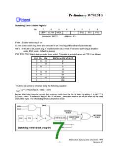
Watchdog Timer
The Watchdog timer is a free-running timer which can be programmed by the user to serve as a
system monitor, a time-base generator or an event timer. It is basically a set of dividers that divide
the system clock. The divider output is selectable and determines the time-out interval. When the
time-out occurs a system reset can also be caused if it is enabled. The main use of the Watchdog
timer is as a system monitor. This is important in real-time control applications. In case of power
glitches or electro-magnetic interference, the processor may begin to execute errant code. If this is
left unchecked the entire system may crash. The watchdog time-out selection will result in different
time-out values depending on the clock speed. The Watchdog timer will de disabled on reset. In
general, software should restart the Watchdog timer to put it into a known state. The control bits that
support the Watchdog timer are discussed below.
- 6 -

 WINBOND [ WINBOND ]