Preliminary W78E378/W78C378/W78C374
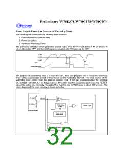
Reset Circuit- Power-low Detector & Watchdog Timer
The reset signals come from the following three sources:
1. External reset input (active low)
2. Power low detect
3. Hardware Watchdog Timer
CC
3.5V
The power-low detection circuit generates a reset signal once the V falls below
for above 10
CC
m
1.8V
4.3V
S or falls below
, and the reset signal is released after V goes up to .
4.3V
3.8V
1.8V
VCC
10uS
Power-low Reset
The purpose of a watchdog timer is to reset the CPU if the user program fails to reload the watchdog
timer within a reasonable period of time known as the "watchdog interval". The clock source of the
watchdog timer comes from the internal system clock. It can be enabled/disabled by set/clear
RESET
WDTEN (bit 5 of CTRL2). For debug purpose, if the WDT reset or power low reset occur, the
pin will be pulled low internally. The pulled-low duration due to WDT reset is about 60/Fosc sec. The
block diagram of the reset circuitry is shown as below.
R:100K
C:0.01u
/RESET
Watchdog
Timer
Reset Logic
EN
WDTEN
External Reset
Power-low
Supervisor
Iol=12mA @Vol=0.45V
- 32 -

 WINBOND [ WINBOND ]