W25Q16DV
the QE bit is set to a 1, the Quad IO2 and IO3 pins are enabled, and /WP and /HOLD functions are
disabled.
WARNING: If the /WP or /HOLD pins are tied directly to the power supply or ground during
standard SPI or Dual SPI operation, the QE bit should never be set to a 1.
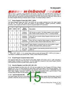
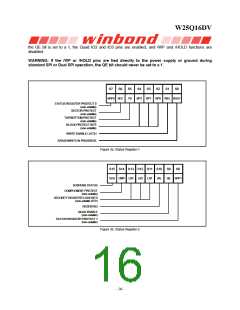
S7
S6
S5
TB
S4
S3
S2
S1
S0
SRP0 SEC
BP2
BP1
BP0 WEL BUSY
STATUS REGISTER PROTECT 0
(non-volatile)
SECTOR PROTECT
(non-volatile)
TOP/BOTTOM PROTECT
(non-volatile)
BLOCK PROTECT BITS
(non-volatile)
WRITE ENABLE LATCH
ERASE/WRITE IN PROGRESS
Figure 3a. Status Register-1
S15 S14 S13 S12 S11 S10
SUS CMP LB3 LB2 LB1 (R)
S9
S8
QE SRP1
SUSPEND STATUS
COMPLEMENT PROTECT
(non-volatile)
SECURITY REGISTER LOCK BITS
(non-volatile OTP)
RESERVED
QUAD ENABLE
(non-volatile)
STATUS REGISTER PROTECT 1
(non-volatile)
Figure 3b. Status Register-2
- 16 -

 WINBOND [ WINBOND ]