Preliminary W24100
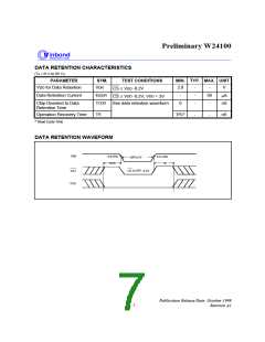
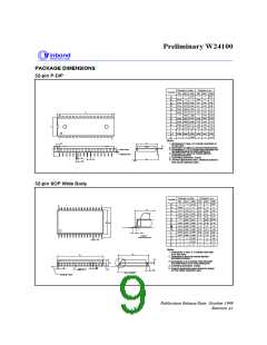
PACKAGE DIMENSIONS
32-pin P-DIP
Dimension in inches
Min. Nom. Max. Min. Nom. Max.
Dimension in mm
Symbol
A
5.33
0.210
0.010
0.150 0.155 0.160 3.81
0.016 0.018 0.41
0.048 0.050 0.054 1.22
0.25
A
A
B
1
3.94
0.46
1.27
0.25
4.06
0.56
1.37
0.36
2
0.022
B1
c
D
E
0.20
0.010 0.014
1.650 1.660
0.008
D
17
32
41.91 42.16
15.49
14.10
2.79
0.610
15.24
13.97
2.54
0.590 0.600
14.99
13.84
0.545 0.550 0.555
E
1
0.110
0.140
15
0.090 0.100
2.29
3.05
0
e
L
a
1
E1
0.120
0
3.30
0.130
3.56
15
17.02
0.630 0.650 0.670 16.00 16.51
0.085
eA
S
2.16
16
1
Notes:
E
S
1. Dimensions D Max. & S include mold flash or
tie bar burrs.
c
2. Dimension E1 does not include interlead flash.
3. Dimensions D & E1 include mold mismatch and
are determined at the mold parting line.
4. Dimension B1 does not include dambar
protrusion/intrusion.
2
A
A
L
A1
Base Plane
Seating Plane
5. Controlling dimension: Inches
6. General appearance spec. should be based on
final visual inspection spec.
B
e1
eA
a
B1
32-pin SOP Wide Body
Dimension in mm
Min. Nom. Max. Min. Nom. Max.
Dimension in Inches
Symbol
3.00
0.118
A
17
32
0.004
0.101 0.106 0.111
0.10
2.57
0.36
0.15
A1
A2
b
e1
2.69
0.41
2.82
0.51
0.014 0.016
0.006 0.008
0.020
0.012
0.20
0.31
c
20.75
11.43
1.42
0.805 0.817
20.45
11.30
1.27
D
E
e
E H
E
11.18
1.12
0.440 0.445 0.450
0.056
0.044 0.050
q
0.546 0.556 0.556 13.87 14.12 14.38
HE
L
L E
0.023
0.039
0.031
0.79
1.40
0.99
0.58
1.19
L
0.063
0.036
0.047 0.055
1.60
0.91
Detail F
1
16
S
y
b
0.10
10
0.004
10
0
0
q
Notes:
1. Dimensions D Max. & S include mold flash
or tie bar burrs.
e1
D
2. Dimension b does not include dambar
protrusion/intrusion.
c
3. Dimensions D & E include mold mismatch
.
A
2
A
and determined at the mold parting line.
4. Controlling dimension: Inches
5. General appearance spec should be based
on final visual inspection spec.
e
S
y
L
E
A
1
See Detail F
Seating Plane
Publication Release Date: October 1999
Revision A1
- 9 -

 WINBOND [ WINBOND ]