Multilayer Ceramic Capacitors
Approval Sheet
APPLICATION NOTES
◙ Storage
To prevent the damage of solderability of terminations, the following storage conditions are recommended:
Indoors under 5 ~ 40°C and 20% ~ 70% RH.
No harmful gases containing sulfuric acid, ammonia, hydrogen sulfide or chlorine.
Packaging should not be opened until the capacitors are required for use. If opened, the pack should be
re-sealed as soon as is practicable. Taped product should be stored out of direct sunlight, which might
promote deterioration in tape or adhesion performance. The product is recommended to be used within 12
months after shipment and checked the solderability before use.
◙ Handling
Chip capacitors are dense, hard, brittle, and abrasive materials. They are liable to suffer mechanical
damage, in the form of cracks or chips. Chip Capacitors should be handled with care to avoid contamination
or damage. To use vacuum or plastic tweezers to pick up or plastic tweezers is recommended for manual
placement. Tape and reeled packages are suitable for automatic pick and placement machine.
◙ Preheat
In order to minimize the risk of thermal shock during soldering, a carefully controlled preheat is required.
The rate of preheat should not exceed 3°C per secon d.
◙ Soldering
Use middy activated rosin RA and RMA fluxes do not use activated flux. The amount of solder in each
solder joint should be controlled to prevent the damage of chip capacitors caused by the stress between
solder, chips, and substrate.
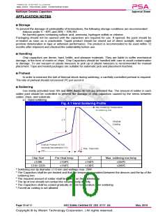
a.) Hand soldering :
Fig. 4.1 Hand Soldering Profile
Chip Size
≤1206
Pre-Heat temp.
≥150°C
∆T
Max. soldering iron temp.
≤150°C
≤130°C
≤350°C
≤280°C
1210~2225
≥150°C
* Soldering iron tip diameter ≤1.0 mm and wattage max. 20W.
* The Capacitors shall be pre-heated and that the temperature gradient between the devices and the tip of the
soldering iron.
* The required amount of solder shall be melted on the soldering tip.
* The tip of iron should not contact the ceramic body directly.
* The Capacitors shall be cooled gradually at room temperature after soldering.
* Forced air cooling is not allowed.
Page 10 of 11
ASC Safety Certified X2_(S3)_011Y_AS
May. 2019

 WALSIN [ Walsin Technology ]