Multilayer Ceramic Capacitors
Approval Sheet
9. RELIABILITY TEST CONDITIONS AND REQUIREMENTS
Standard
Method
No.
Item
Test Condition
Requirements
1. Visual
IEC 60384-1
* No remarkable defect.
examination 4.1
and
* Dimensions to confirm to individual specification
sheet.
Dimensions
2. Capacitance IEC 60384-1 * Class I : (C0G)
* Capacitance is within specified tolerance.
* CR means rated capacitance for conform to the E6
series of preferred values given in IEC 60063.
4.2.2
Cap.≤1000pF, 1.0±0.2Vrms, 1MHz±10%.
Cap.>1000pF, 1.0±0.2Vrms, 1KHz±10%.
3. D.F.
IEC 60384-1
* Class II : (X7R)
1.0±0.2Vrms, 1KHz±10%.
(Dissipation 4.2.3
Factor)
Dielectric
Q/D.F.
Remark
Q≥1000
Cap.≥30pF
Cap.<30pF
Tangent
loos angle
of
Class I (C0G)
Q≥400+20C
Class II (X7R) D.F.≤2.5%
4. Temperature IEC
Coefficient 60384-21/22
4.6
With no electrical load.
T.C.
C0G(NP0)
X7R
Capacitance Change
Within ±30ppm/℃
Within ±15%
T.C.
Operating Temp
-55~125°C at 25°C
-55~125°C at 25°C
C0G(NP0)
X7R
5. Voltage proof IEC 60384-14 * To apply voltage :
* No evidence of damage or flash over during
test.
(Dielectric
Strength)
4.2.1
X Capacitor : 1075Vdc (4.3UR).
* Duration : 60 sec.
* The charge current shall not exceed 0.05A.
* The voltage shall be raised from the near zero to
the test voltage a rate not exceeding
150V(r.m.s.)/sec.
6. Insulation
IEC
Dielectric
Requirements
Rated
Vol.(V)
>500
Apply
Voltage Current Time
500Vdc ≤50mA 60 sec.
Charge Charge
Resistance 60384-21/22
≥100GΩ or RxC≥1000Ω-F,
whichever is smaller
≥10GΩ or RxC≥500Ω-F,
whichever is smaller
4.5.3
Class I (C0G)
Class II (X7R)
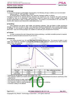
7. Solderability IEC
* Solder temperature: 235±5°C(0201~1210).
* 75% min. coverage of all metalized area.
60384-21/22 * Solder temperature: 245±5°C(1808~2225).
4.10 * Dipping time : 2±0.5 sec.
8. Resistance IEC 60384-14 * Solder temperature : 260±5°C.
Dielectric I.R.
Class I
Cap. Change
Q/D.F.
to Soldering 4.4
* Dipping time : 10±1 sec.
Within ±2.5% or
≥1GΩ ±0.25pF, whichever
Heat
IEC
60384-21/22
4.9
* Preheating : 120 to 150°C for 1 minute before
immerse the capacitor in a eutectic solder.
* Measurement to be made after keeping at room
temperature for 24±2 hrs.
≤100% of
initial
requireme
nt
(C0G)
is larger
Class II
(X7R)
≥1GΩ Within ±7.5%
9. Temperature IEC
* Conduct the five cycles according to the
temperatures and time.
Cycle
60384-21/22
4.11
Step
Temp.(°C)
Time(min.)
30±3
Cap. Change Q/D.F.
Within ±2.5%
Dielectric I.R.
Class I
Min. operating
temp. +0/-3
1
2
3
4
≤1.0(Q) ×
or ±0.25pF,
whichever is
larger
Room temp.
2~3
initial
requirement
To meet
(C0G)
initial
Max.operating
temp. +3/-0
30±3
require
ment
≤1.5(D.F.) ×
Within ±7.5% initial
requirement
Class II
(X7R)
Room temp.
2~3
* Measurement to be made after keeping at room
temperature for 24±2 hrs.
Page 6 of 11
ASC Safety Certified X2_(S3)_011Y_AS
May. 2019

 WALSIN [ Walsin Technology ]