VSC6134
Datasheet
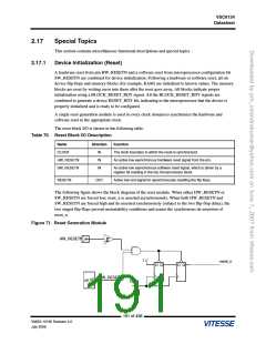
Figure 74. Interrupt Generation and Clear Timing Example
Real Condition
Condition Status
Block Interrupt
Condition Status FSM (Software)
1
Read A
Read C Read D
Read B
Read A: Read global block interrupt register to determine which block is causing interrupt
Read B: Read block interrupt status register (this clears block interrupt/interrupt status register)
Read C: Read global block interrupt register to determine which block is causing interrupt
0
Read D: Read block interrupt status register (this clears block interrupt/interrupt status register)
Reset Device
2.17.3
Performance Monitor One-Second Pulse
The following figure shows how the internal one-second pulse is generated.
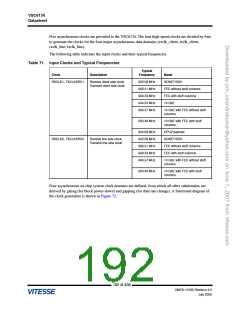
Figure 75. One-Second Pulse Source
SW_SECONDP
0
1
RXCLK_CLIENT (RXCLK1/4)
1000
0100
0010
0001
Mux
SECONDP_CLK
TXCLK_CLIENT (TXCLKSRC1/4)
Counter
SECONDP_CNT[31:0]
TXCLK_LINE (TXCLKSRC0/4)
RXCLK_LINE (RXCLK0/4)
SECP_SOURCE_SEL
SECP_CLK_SEL[3:0]
There are two sources for the one-second pulse:
●
For control under software (that is, SECP_SOURCE_SEL = 0), the microprocessor configuration
bit, SW_SECONDP, is toggled from 0 to 1 to generate the one-second pulse.
●
For automatic internal generation of the one second pulse (that is, SECP_SOURCE_SEL = 1), the
source of the one-second pulse is selected using the configuration bits SECP_CLK_SEL[3:0],
selecting one of the four internal divide-by-four clocks. For more information for the four clock
domains, 155 MHz add path SDH clock, 155 MHz drop path SDH clock, 195 MHz add path FEC
clock, or 195 MHz drop path FEC clock, see Figure 72, page 193 and Table 71, page 192. A 32-bit
programmable counter, programmed using the configuration bits SECONDP_CNT[31:0], divides
the selected internal clock to generate the one-second pulse. SECONDP_CNT[31:0] is
programmed with a count equal to half the clock frequency of the source clock. For example, if the
195 of 438
VMDS-10185 Revision 4.0
July 2006

 VITESSE [ VITESSE SEMICONDUCTOR CORPORATION ]