VSC6134
Datasheet
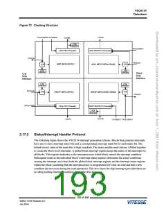
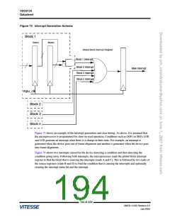
Figure 73. Interrupt Generation Scheme
Block 1
Status
Masks
Global Block Interrupt Register
Block 1 Interrupt
Block 2 Interrupt
Block 3 Interrupt
Block n Interrupt
Main Interrupt
mpu_clk
Block 2
Block 3
Block n
Figure 73 shows an example of the interrupt generation and clear timing. As above, it is assumed that
the microprocessor is programmed for clear-on-read operation. Conditions such as OOF (or SEF), LOF,
and LOS generate an interrupt when there is a change in their state. For example, an interrupt is
generated when the device goes out of frame alignment and another is generated when the device goes
into frame alignment.
Figure 74 shows two interrupts caused by the device detecting a condition and then detecting the
condition going away. Following both interrupts, the microprocessor reads the global block interrupt
register to find the block that is sourcing the interrupts (reads A and C). This is followed by two reads of
the source registers (reads B and D) to find the condition that is causing the interrupts and optionally
clearing the interrupt status bit and the interrupt.
194 of 438
VMDS-10185 Revision 4.0
July 2006

 VITESSE [ VITESSE SEMICONDUCTOR CORPORATION ]