VSC6134
Datasheet
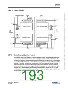
Figure 72. Clocking Structure
TXCLKSRC0VCOSRC0
VCO01
VCO00
LOCK
Monitor
RXCLK0DIV
RXCLK1
ADD FEC Prescaler
ADD SDH/OTU Prescaler
TXCLK0
ADD StFEC/EFEC
ADD StFEC/SDH/10GbE
1/4
1/4
LOCK
LOCK
Monitor
Monitor
Client
Side
Interface
Line
Side
Interface
MLoOnCitKor
1/4
MLoOnCitKor
1/4
RXCLK0
DROP StFEC/EFEC
DROP StFEC/SDH/10GbE
TXCLK1
RXCLK1DIV
Drop FEC Prescaler
DROP SDH/OTU Prescaler
MLoOnCitKor
VCO10
VCO11
VCOSRC1 TXCLKSRC1
2.17.2
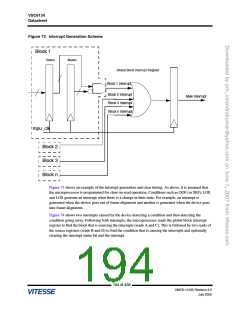
Status/Interrupt Handler Protocol
The following figure shows the VSC6134 interrupt generation scheme. Blocks that generate interrupts
have one or more interrupt status bits and a corresponding interrupt mask bit for each status bit. The
default (reset) value of the mask bits is high (masked). The status and the mask bits are ANDed together
to create the block-level interrupts. A global block interrupt register keeps the status of the interrupts for
all blocks. This register indicates to the microprocessor which block caused the interrupt condition.
Subsequent reads to the individual block’s interrupt status registers determine the actual conditions
causing the interrupt, and clears both the global block interrupt register and the interrupt status register
within the block (assuming that the microprocessor is programmed for clear-on-read and that a new
condition did not occur during the read operation). This also clears the chip interrupt (provided there are
no other pending interrupt conditions from other blocks).
193 of 438
VMDS-10185 Revision 4.0
July 2006

 VITESSE [ VITESSE SEMICONDUCTOR CORPORATION ]