VSC6134
Datasheet
desired clock cycle for SECONDP_CLK is 1 second and SECP_CLK_SEL[3:0] selects
RXCLK_CLIENTRXCLK1 / 4 as the clock source for the counter (with SONET input data), then
the programmed count must be: 155, 520, 000 / 2 = 77, 760, 000 (this is done to produce a clock
with a 50% duty cycle).
The one-second pulse is not required to have a 50% duty-cycle. Therefore, in the case of the software
generated one-second pulse, the microprocessor is not required to write regularly to create a 50% duty
cycle.
2.17.4
Loss of Input Clock (LOCK) Monitor
This block detects and reports, using a maskable interrupt status bits, the loss of input clock (LOCK)
when the clock is stuck high or low for an interval T. The detection time of T is based on the
microprocessor clock (MPU_CLK), and is less than 10 msec for a 16-MHz MPU_CLK clock. The
status bits (xx_LOCKS) and the associated interrupt mask bits (xx_LOCKM) are used to indicate the
loss of clock status and to generate an interrupt. Microprocessor clock MPU_CLK is required to detect
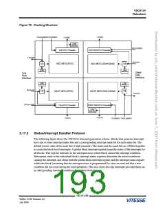
loss of clock xx_LOCKS status on any of the six clock inputs. For more information, see Figure 72,
page 193. It is assumed that the MPU_CLK signal is always present.
The loss of input clock monitor block I/O is shown in the following table.
Table 72. Loss of Clock Monitor Block I/O Description
Name
Direction
Function
RESETN
CLK
IN
IN
IN
Active low reset
155 MHz system clock
CLR_RD_WRN
Control signal indicating whether status registers are cleared on-read or
on-write
MPU_CLK
IN
IN
Microprocessor clock
MPU_RESETN
MPU_RDENA
MPU_ADDR[11:0]
LOCK_INT
Active low MPU_CLK reset
IN
Microprocessor read enable signal
Microprocessor address bus
IN
OUT
OUT
Loss of clock monitor active high interrupt signal
Loss of clock monitor data acknowledgement pulse
LOCK_DTK
All input clocks are monitored for loss of clock. All the mask and status bits are included in the global
microprocessor registers 14 and 15 shown in Table 412, page 374 and Table 413, page 375.
196 of 438
VMDS-10185 Revision 4.0
July 2006

 VITESSE [ VITESSE SEMICONDUCTOR CORPORATION ]