VSC6134
Datasheet
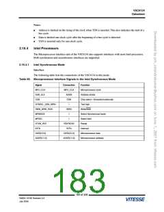
Interface
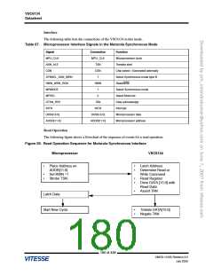
The following table lists the connections of the VSC6134 in this mode.
Table 67. Microprocessor Interface Signals in the Motorola Synchronous Mode
Signal
Connection
Function
MPU_CLK
ASN_ALE
CSN
MPU_CLK
Microprocessor clock
Transfer start
TSN
CSN
Chip select—Generated externally
Select Synchronous mode type B
Read/write
SYNSEL_DSN_WRN
RWN_WRN_RDN
MPMODE
MPSEL
1
RWN
1
Select Synchronous mode
Select Motorola
0
DTKN_RDY
INTN
TAN
Data acknowledge
Interrupt
INTN
DATA[15:0]
ADDR[11:0]
DATA[15:0]
ADDR[11:0]
Microprocessor data
Microprocessor address
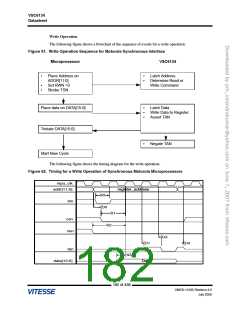
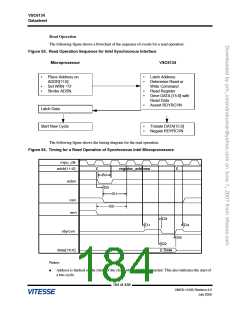
Read Operation
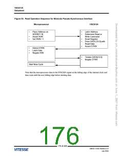
The following figure shows a flowchart of the sequence of events for a read operation.
Figure 59. Read Operation Sequence for Motorola Synchronous Interface
Microprocessor
VSC6134
•
Place Address on
ADDR[11:0]
Set RWN =1
Strobe TSN.
•
•
Latch Address
Determine Read or
Write Command
Read Register
Drive DATA [15:0] with
Read Data
•
•
•
•
•
Assert TAN
Latch Data
Start New Cycle
•
•
Tristate DATA[15:0]
Negate TAN
180 of 438
VMDS-10185 Revision 4.0
July 2006

 VITESSE [ VITESSE SEMICONDUCTOR CORPORATION ]