VSC6134
Datasheet
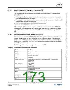
Table 65. External Microprocessor Interface Signals (continued)
Signal
Function
DATA[15:0]
ADDR[11:0]
Microprocessor data
Microprocessor address
2.16.2
Configuration Bits
The MPIU has two configuration bits that determine its behavior:
●
DTK_TRI_PRG (DEFAULT = 0)
This bit determines when the MPIU tristates the data acknowledge (DTKN_RDY) signal. When
DTK_TRI_PRG is set to 0 the MPIU starts driving the DTKN_RDY signal when it determines that
the current bus cycle is intended for the VSC6134. This mode is used for microprocessors that have
dedicated chip select signals that are de-asserted at the same time as the signals that indicate an end
of cycle. Tristating the DTKN_RDY signal one-half clock cycle after the DTKN_RDY is
de-asserted assures that there is adequate time to drive the PCB trace to the de-asserted value.
In this mode the behavior of the DTKN_RDY signal is as follows:
-
Motorola pseudo-synchronous: DTKN_RDY is tristated on the rising edge that detects an end
of bus cycle.
-
Motorola synchronous and Intel synchronous: DTKN_RDY is tristated on the falling edge
after the microprocessor terminates the bus cycle or the DTKN_RDY signal is de-asserted.
For systems where the chip select signal is decoded from the address bus of the MPIU,
DTK_TRI_PRG can be set to 1. In this mode, the MPIU drives the DTKN_RDY signal as long as
CSN is asserted.
●
AUTO_DTK_GEN (DEFAULT = 0)
This bit is used to enable an automatic data acknowledge generator in the MPIU. In the normal mode,
AUTO_DTK_GEN is set to 0, and the block that is being accessed by the microprocessor is responsible
for generating its own data acknowledge signal.
When AUTO_DTK_GEN is set to 1, a counter generates an automatic data acknowledge signal
16 MPU_CLK clock cycles after the MPU_RDENA or MPU_WRENA line is asserted. This causes the
microprocessor and the MPIU to end its current bus cycle.
2.16.3
Motorola Processors
The MPIU can interface with the following types of Motorola microprocessors:
The VSC6134 can interface with the Motorola processors in two different modes:
●
●
Pseudo-synchronous
Synchronous
The SYNSEL_DSN_WRN pin is used to select between the two synchronous modes.
174 of 438
VMDS-10185 Revision 4.0
July 2006

 VITESSE [ VITESSE SEMICONDUCTOR CORPORATION ]