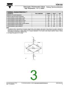
VO615A
Optocoupler, Phototransistor Output,
High Temperature, 110 °C, Rated
Vishay Semiconductors
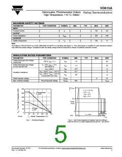
ELECTRICAL CHARACTERISTICS (1)
PARAMETER
TEST CONDITION
SYMBOL
MIN.
TYP.
MAX.
UNIT
INPUT
Forward voltage
IF = 50 mA
VF
Cj
1.25
50
1.6
V
Junction capacitance
OUTPUT
V
R = 0, f = 1 MHz
pF
Collector emitter voltage
Emitter collector voltage
Collector emitter cut-off current
COUPLER
I
C = 1 mA
E = 100 µA
CE = 20 V, If = 0, E = 0
VCEO
VECO
ICEO
70
7
V
V
I
V
10
100
0.3
nA
Collector emitter saturation voltage
IF = 10 mA, IC = 1 mA
VCEsat
fc
V
V
CE = 5 V, IF = 10 mA,
Cut-off frequency
110
0.3
kHz
pF
RL = 100 Ω
Coupling capacitance
f = 1 MHz
Ck
Note
amb = 25 °C, unless otherwise specified.
T
Minimum and maximum values are testing requirements. Typical values are characteristics of the device and are the result of engineering
evaluation. Typical values are for information only and are not part of the testing requirements.
CURRENT TRANSFER RATIO
PARAMETER
TEST CONDITION
PART
SYMBOL
CTR
CTR
CTR
CTR
CTR
CTR
CTR
CTR
CTR
CTR
CTR
CTR
CTR
CTR
MIN.
13
TYP.
30
MAX.
UNIT
%
VO615A-1
VO615A-2
VO615A-3
VO615A-4
VO615A
22
45
%
VCE = 5 V, IF = 1 mA
34
70
%
56
90
%
50
600
150
300
160
260
400
80
%
VO615A-5
VO615A-6
VO615A-7
VO615A-8
VO615A-9
VO615A-1
VO615A-2
VO615A-3
VO615A-4
50
%
100
80
%
IC/IF
VCE = 5 V, IF = 5 mA
%
130
200
40
%
%
%
63
125
200
320
%
V
CE = 5 V, IF = 10 mA
100
160
%
%
www.vishay.com
4
For technical questions, contact: optocoupler.answers@vishay.com
Document Number: 81753
Rev. 1.0, 04-Mar-08

 VISHAY [ VISHAY ]