TMC5130A DATASHEET (Rev. 1.14 / 2017-MAY-15)
6
step & dir input optional current scaling
5VOUT
RREF
Optional for internal
current sensing.
RREF=9K1 allows for
maximum coil current.
+VM
100n
TMC 5130A / TMC 2130
Stepper motor driver
VS
+VM
step multiplier
microPlyer
VCP
CPI
OA1
Half Bridge 1
Half Bridge 2
DAC Reference
IREF
100n
22n
charge pump
Standstill
current
reduction
ISENSE
ISENSE
CPO
VSA
OA2
BRA
5V Voltage
regulator
5VOUT
&
p
C
100n
e
h
t
t
o
S
l
o
o
4.7µ
2R2
c
p
o
i
h
VCC
RS
2R2 and 470n are optional
filtering components for
best chopper precision
l
a
e
PU=166K pullup resistor to VCC
PD=166k pull down resistor to GND
t
s
r
e
v
470n
GNDP
r
d
r
PU
CSN
SCK
t
IREF
o
m
current
PU
DRV_ENN
DAC
DAC
comparator
spreadCycle &
stealthChop
Chopper
RS=0R15 allows for
maximum coil current;
Use low inductance
SMD resistor type.
Tie BRA and BRB to
GND for internal
SPI interface
SPI™
PU
SDI/NAI
programmable
sine table
4*256 entry
N
Control register
set
PU
SDO/NAO
x
S
e
c
a
f
r
Stepper driver
Protection
& diagnostics
e
t
n
2 phase
stepper
motor
current sensing
I Single wire
PD
interface selection
(-TA package only)
SW_SEL
current
interface
(-TA pckg only)
comparator
GNDP
IREF
PDD=100k pulldown
PMD=50k to VCC/2
single wire
UART
coolStep™
RS
PDD
SWP_DIAG1
SWN_DIAG0
Opt. interrupt out
BRB
PMD
Opt. poscomp out
stallGuard2™
Diff. Tranceiver
OB2
Half Bridge 2
Half Bridge 1
INT & position
pulse output
ISENSE
dcStep™
opt. ext. clock
10-16MHz
CLK_IN
VCC_IO
OB1
VS
CLK oscillator/
selector
+VIO
ISENSE
3.3V or 5V
I/O voltage
100n
+VM
100n
dcStep control
Tie DCEN to GND if
dcStep is not used
leave open
opt. driver enable
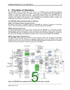
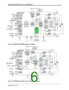
Figure 1.2 TMC5130A STEP/DIR application diagram
step & dir input optional current scaling
5VOUT
RREF
Optional for internal
current sensing.
RREF=9K1 allows for
maximum coil current.
+VM
F
=
60ns spike filter
CFG3
TMC 5130A / TMC 2130
Standalone Stepper
motor driver
100n
VS
+VM
CFG1
CFG2
step multiplier
microPlyer
VCP
CPI
OA1
Half Bridge 1
Half Bridge 2
DAC Reference
IREF
100n
22n
charge pump
Standstill
current
reduction
CFG6
ISENSE
ISENSE
CPO
VSA
OA2
BRA
5V Voltage
regulator
&
p
e
5VOUT
e
l
c
C
100n
y
h
r
C
t
o
d
a
t
a
e
r
4.7µ
2R2
p
s
o
i
h
VCC
RS
2R2 and 470n are optional
filtering components for
best chopper precision
l
e
t
s
r
470n
GNDP
v
r
d
TG= toggle with 166K resistor between VCC
and GND to detect open pin
IREF
o
TG
m
CFG0
CFG4
CFG5
CFG0
CFG1
CFG2
CFG3
CFG4
CFG5
current
CFG1
CFG2
DAC
DAC
comparator
spreadCycle &
stealthChop
Chopper
TG
RS=0R15 allows for
maximum coil current;
Tie BRA and BRB to
GND for internal
CFG1
CFG2
N
S
TG
sine table
4*256 entry
x
Configuration
interface
TG
TRISTATE configuration
(GND, VCC_IO or open)
current sensing
Stepper driver
Protection
with TRISTATE
detection
2 phase
stepper
motor
DRV_ENN
TG
current
& diagnostics
comparator
TG
TG
GNDP
IREF
Opt. driver
enable input
DRV_ENN_CFG6
RS
e
c
a
f
r
e
t
n
PDD=100k pulldown
PMD=50k to VCC/2
BRB
I
PDD
DIAG1
DIAG0
Index pulse
Driver error
OB2
Half Bridge 2
Half Bridge 1
PMD
Status out
(open drain)
ISENSE
opt. ext. clock
10-16MHz
CLK_IN
OB1
VS
CLK oscillator/
selector
+VIO
ISENSE
3.3V or 5V
I/O voltage
VCC_IO
100n
+VM
100n
leave open
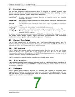
Figure 1.3 TMC5130A standalone driver application diagram
www.trinamic.com

 TRINAMIC [ TRINAMIC MOTION CONTROL GMBH & CO. KG. ]