TMC5130A DATASHEET (Rev. 1.14 / 2017-MAY-15)
5
1 Principles of Operation
The TMC5130A motion controller and driver chip is an intelligent power component interfacing
between CPU and stepper motor. All stepper motor logic is completely within the TMC5130A. No
software is required to control the motor – just provide target positions. The TMC5130A offers a
number of unique enhancements which are enabled by the system-on-chip integration of driver and
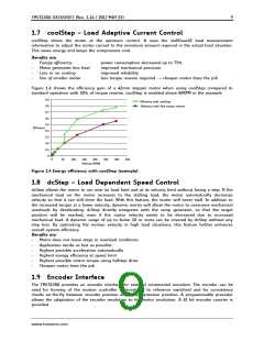
controller. The sixPoint ramp generator of the TMC5130A uses stealthChop, dcStep, coolStep, and
stallGuard2 automatically to optimize every motor movement.
THE TMC5130A OFFERS THREE BASIC MODES OF OPERATION:
MODE 1: Full Featured Motion Controller & Driver
All stepper motor logic is completely within the TMC5130A. No software is required to control the
motor – just provide target positions. Enable this mode by tying low pin SD_MODE.
MODE 2: Step & Direction Driver
An external high-performance S-ramp motion controller like the TMC4361 or a central CPU generates
step & direction signals synchronized to other components like additional motors within the system.
The TMC5130A takes care of intelligent current and mode control and delivers feedback on the state of
the motor. The microPlyer automatically smoothens motion. Leave open SD_MODE and SPI_MODE.
MODE 3: Simple Step & Direction Driver
The TMC5130A positions the motor based on step & direction signals. The microPlyer automatically
smoothens motion. No CPU interaction is required; configuration is done by hardware pins. Basic
standby current control can be done by the TMC5130A. Optional feedback signals allow error detection
and synchronization. Enable this mode by tying low pin SPI_MODE.
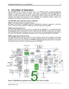
reference / stop switches
optional current scaling
5VOUT
RREF
Optional for internal
current sensing.
RREF=9K1 allows for
maximum coil current.
+VM
TMC 5130A
Stepper motor driver /
controller
100n
VS
reference switch
processing
+VM
VCP
CPI
OA1
Half Bridge 1
Half Bridge 2
DAC Reference
IREF
100n
22n
charge pump
ISENSE
ISENSE
CPO
Step &
Direction pulse
generation
linear 6 point RAMP
generator
VSA
OA2
BRA
5V Voltage
regulator
5VOUT
&
p
e
t
100n
l
o
r
S
t
n
l
o
o
4.7µ
o
2R2
c
c
p
r
e
o
n
h
o
i
VCC
C
t
RS
h
o
t
2R2 and 470n are optional
filtering components for
best chopper precision
l
M
PU=166K pullup resistor to VCC
a
e
t
s
470n
GNDP
v
PD=166k pull down resistor to GND
i
r
d
r
PU
CSN
SCK
o
t
IREF
o
m
current
PU
DRV_ENN
DAC
DAC
comparator
spreadCycle &
stealthChop
Chopper
RS=0R15 allows for
maximum coil current;
Use low inductance
SMD resistor type.
Tie BRA and BRB to
GND for internal
SPI interface
SPI™
PU
SDI/NAI
programmable
sine table
4*256 entry
N
Control register
set
PU
SDO/NAO
x
S
e
c
a
f
r
Stepper driver
Protection
& diagnostics
e
t
n
2 phase
stepper
motor
current sensing
I Single wire
PD
interface selection
(-TA package only)
SW_SEL
current
interface
(-TA pckg only)
comparator
GNDP
IREF
PDD=100k pulldown
PMD=50k to VCC/2
single wire
UART
Opt. interrupt out
coolStep™
RS
PDD
SWP_DIAG1
SWN_DIAG0
BRB
PMD
Opt. poscomp out
stallGuard2™
Diff. Tranceiver
OB2
Half Bridge 2
Half Bridge 1
INT & position
pulse output
ISENSE
dcStep™
opt. ext. clock
10-16MHz
CLK_IN
VCC_IO
OB1
VS
CLK oscillator/
selector
Encoder
unit
B
+VIO
A
N
ISENSE
3.3V or 5V
I/O voltage
100n
+VM
100n
Optional incremental
encoder inputs
leave open
opt. driver enable
Figure 1.1 TMC5130A basic application block diagram with motion controller
www.trinamic.com

 TRINAMIC [ TRINAMIC MOTION CONTROL GMBH & CO. KG. ]